Basic Pneumatic – Introduction
Introduction Overview:
Pneumatics is about using compressed air “to make something happen.”
The word Pneu is Greek meaning wind, breath or air. Pneumatic equipment refers to those items that use or are driven by air. Air has no definite shape or volume; it takes on the shape and expands to fill its vessel regardless of size.
Think of blowing up a balloon !!!
Compressed air is the air we breathe squeezed into a small space under pressure. You might remember that air under pressure possesses potential energy which can be released to do useful work.
A pneumatic system consists of a group of components together so that a signal (compressed air) is passed through the system to make something happen at the output.
Understanding pneumatics is very simple. All you have to do is learn how a few basic components work. There are two main groups.
Pneumatic systems are found throughout any food plant and other manufacturing facilities.
Compressed air is also used to drive many instruments and hand tools.
In this unit, you will learn the basic components of a pneumatic system and how to work with pneumatic systems safely.
Always treat compressed air systems with respect! A jet of compressed air directed onto the body may introduce air into the bloodstream and could produce blindness or other eye injuries if directed to the face. Always wear safety glasses and gloves!
Always follow the proper LOTO procedures.
Objectives:
The information, activities, and practice provided during this unit will enable you to:
- Describe the hazards and safety precautions for a pneumatic system.
- Describe the function of the components of the pneumatic system.
- Identify the basic components of a pneumatic system.
Air Pressure Source System:
Below is a picture of one of our compressor units that produces compressed air needed to operate the equipment within the factory. The compressor room has storage tanks required to maintain the volume of compressed air for the factory.
Compressed air contains impurities, and much attention must be paid to those in suspension as they may cause failures in the pneumatic controls (water, dust, rust, etc.)

Air Filter, Pressure Regulator and Oiler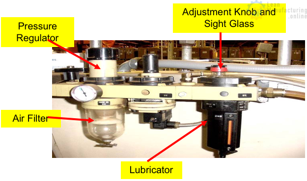
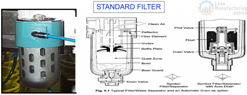
Air Filter:
An Air Filter makes sure the air being used is free of contamination. The filter prevents foreign objects, such as water or dirt,, from entering the valve or cylinder, causing damage.
Pressure Regulator:
These are used to set the required pressure to run our machines.
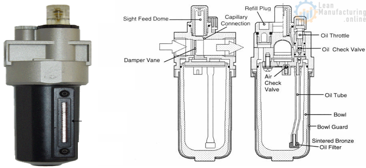
Lubricator:
The lubricator aims to provide a lubricating oil mist to the air-driven device. The lubricator consists of a reservoir filled with oil, a flow-adjusting knob, and a sight glass indicating the oil flow rate. Not all systems have an oiler.
Regulator
A regulator is a device that controls the maximum supply pressure to a compressed air user. Regulation of pressure is necessary. Inspection: Ensure the pressure is steady, and the adjusting knob is functional.

Basic Pneumatic – Pressure Gauge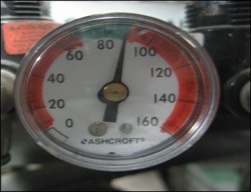
Pressure gauges indicate the operating pressure of a system in PSI (Pounds Per Square Inch).
Gauges come in many different sizes, styles and pressure ranges.
Inspection: Ensure the operating pressure is reading in the green demarcated area. If not, the air pressure is incorrect for the sub-system.
Lubricators
The pneumatic elements (cylinders, valves, etc.) have mobile parts that need lubrication. So that they are sufficiently and continually lubricated, a certain quantity of oil is added to the compressed air using a lubricator.
The lubricator has the task of supplying the pneumatic elements with lubrication. Advantages of lubrication:
- Notable decrease in wear;
- Decrease in losses through friction;
- Corrosion protection;
- Inspection: Ensure that the lubricator has the proper oil level.
Inspection:
Filters are a must to keep systems operating at their potential.
Carefully drain any foreign material and/or moisture out of the trap bowl.
Ensure the filter is not plugged by checking the correct downstream pressure while the equipment runs.
Basic Pneumatic – Care and Maintenance
Mounted properly – Pneumatics are hard on themselves and may come loose from the mounting. Make sure all lines are secured and fasteners are tight.
Air Leaks – Listen for any air leaks and report them immediately to your maintenance department.
Air Gauges – Many pneumatic systems are designed to maintain 100 psi, with some pneumatic systems rated at 175 to 200 psi. Make sure air gauges are at the appropriate pressure level. If not, report them immediately to your Mechanic. Adjust the gauge to the appropriate visual control setting. Air Gauges come in various sizes, colours, pressure ranges, and styles. This is determined by where you want to use it and the operating pressure.
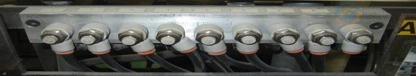
Pipe, Fittings and Shut-off Valves:
Pipes come in many sizes, shapes, and types. Depending on the application, piping is made of steel, plastic, and rubber.
Fittings also come in many different types. Some require a nut with an insert to hold the fitting and pipe together, while others press into each other. This also depends on what it is used for and where it is used.
Shut-off Valves are used to turn the air pressure off in a system. They come in a variety of types and sizes. The most commonly used are Dump Valves, Ball Valves and Gate Valves.

Basic Pneumatic – Introduction

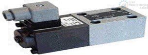
Solenoid Valve
Directional Control Valves are just as their name implies. They control the direction of the air goes by channelling it to different ports. They are often used to control air cylinders. Like cylinders, they come in a variety of sizes and shapes. The valves have specific applications depending on their design.
Flow Control Valve
Flow Control Valves control the speed at which an air cylinder moves when air is applied.
The valve can be adjusted by turning a knob. It controls the air in one direction and allows it to flow without restriction in the other or opposite direction. Proper adjustment of these controls will extend the life of the cylinder by controlling its speed.
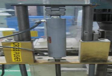
Air Cylinders are the part of a pneumatic system that performs a task, such as moving a part of a machine, lifting or lowering, or even as little as applying pressure to hold something in place.
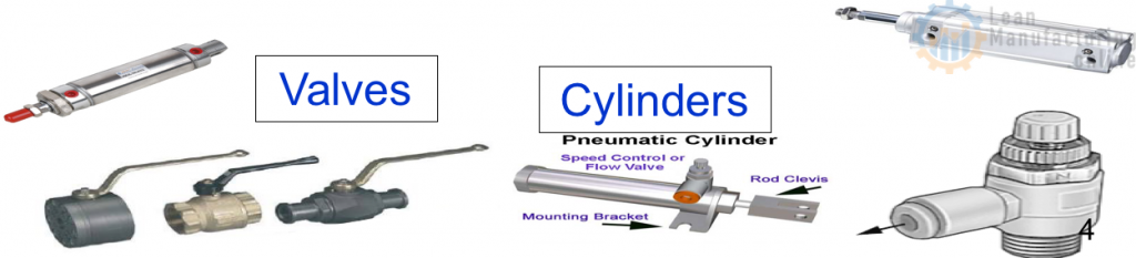
Basic Pneumatic – Valves

There are many types of valves in a compressed air system. Each has its special purpose:
Ball valves are usually for on/off applications.
Flow Control Valves are for controlling the flow of air. And the speed of the cylinder or device it is attached to.
Dump valves are shut-off valves that also bleed off any residual air pressure. These are used for safety shut-off valves.
Exhaust Mufflers are for noise reduction.
Basic Pneumatic – Solenoid
Solenoid valves are commonly used in the plant and use an electromagnet to move the internal piston from one position to another, which in turn causes the air cylinder to move in different directions. In a single solenoid valve, the piston moves in one direction by an internal spring when power is applied to the solenoid and in the other direction. Double solenoid valves move the piston where power is being applied to the solenoid. It will remain in this position until the other solenoid is activated.
Single solenoid 2 position valve
Double solenoid 2 position valve

Basic Pneumatic – Cylinders
Air Cylinders:
Air Cylinders are part of a pneumatic system that performs a task, such as moving a part of a machine, lifting or lowering, or even as little as applying pressure to hold something in place.
Single acting cylinder
Double acting cylinder
Basic Components of a Pneumatic Valves:
Valves control the switching and routing of air in a pneumatic system. Valves not only have to control the flow of the compressed air, they also have to control the flow of the exhaust to the atmosphere. Two main types of valves are used in pneumatic switching circuits: 2/3 valves and 2/5 valves.

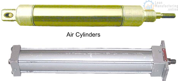
Air Cylinders:
They come in a variety
of sizes and shapes and are made by
numerous companies. It is important to
understand the basic principle of an
air cylinder.
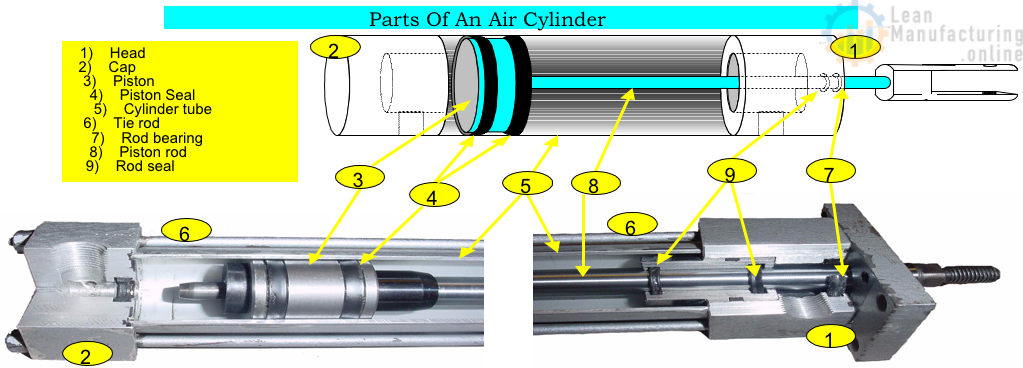
Basic Components of a Pneumatic Cylinder:
Cylinders convert the energy in the compressed air into straight motion (forward and backward or up and down). The air enters the cylinder and pushes a piston from one end to the other.

Basic Components of a Pneumatic Cylinder:
Single Acting Cylinders:
A single-acting cylinder has only one air connection, while a double-acting acting has two.
With a single-acting cylinder, the piston is pushed outwards by the pressure of the air. When the air supply is removed, and the air inside the cylinder can escape (we call this the exhaust), the piston moves back to its resting position using a compressed spring.
Double Acting Cylinders:
The double-acting cylinder has two air connections. When compressed air is sent to one side, and the other is allowed to exhaust, the piston is pushed to one end of the cylinder. When air is sent to the other side, and the first side is allowed to exhaust, the piston is pushed back. This type of cylinder is more powerful on the return stroke than the single-acting cylinder.
Basic Pneumatic – Safety
System Hazards:
The pneumatic system can pose two potential safety hazards:
* Pinch Points
* Stored Energy
Both can potentially cause bodily and equipment harm. The Pneumatic system is composed of both moving and non-moving components. Particularly where there are air cylinders (moving parts). Pinch points are one of the primary safety concerns. For example: Injury could result if your hand or any other part of your body gets caught between the shaft of an air cylinder and another piece of equipment. Therefore, the importance of following LOTO procedures is essential!
In regards to non-moving components of the pneumatic system, stored energy becomes a primary concern. When air is under pressure, there is the possibility of the air being released unexpectedly, potentially causing bodily harm or damage to equipment. For example: stored energy can also cause the cylinder to move in the opposite direction once air pressure is released.
Air Leaks:
If the system experiences a sudden loss of pressure or a hissing noise, there is a leak. The leak could indicate a fractured pipe or broken hose. Personnel and equipment could be in danger if the pipe/hose ruptures or blows apart.
Never attempt to find a leak by handing over the piping without the proper PPE. Due to high pressure, the compressed air could enter the hand through the skin, causing a serious injury.
Never tighten air line fittings while they are under pressure. Isolate the air line and bleed off the air pressure before making any repairs.
Swollen areas on airlines are an indication of wear and could burst. They must be repaired or replaced immediately.
Oil and moisture are mixed with the air as compressed air is produced. When the compressed air leaves the compressor, the oil and water mixture may be a fine mist. The oil contained in the mist is flammable. A spark or open flame can ignite the air and oil moisture. In the event of a leak in the system near the compressor, keep all open flames and sparks away. There are separators and a dryer to remove the oil and moisture from the air before it leaves the mechanical room.
There is always electrical wiring around the components of a pneumatic system. Ensure that any loose or bare wiring is F – Tagged immediately.
Broken or Damaged wiring could create a spark that could ignite the oil and air mixture.
Basic Pneumatic – Vibrators
Pneumatic vibrators use compressed air to force a metal ball to spin in a circle at very high speeds. This creates vibration, which can help components feed down the line in certain applications.
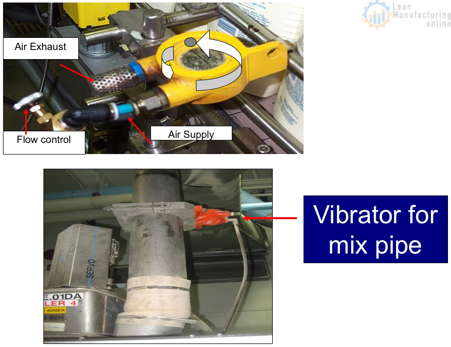
Inspection: To avoid waste, set the airflow at the lowest rate that still does the job.
Vacuum System
Vacuum Systems have many uses, such as opening shippers for packers, pulling cartons, transferring pouches from the gripper chain, etc.
Here are some examples of vacuum pumps that are used in a food manufacturing factory.
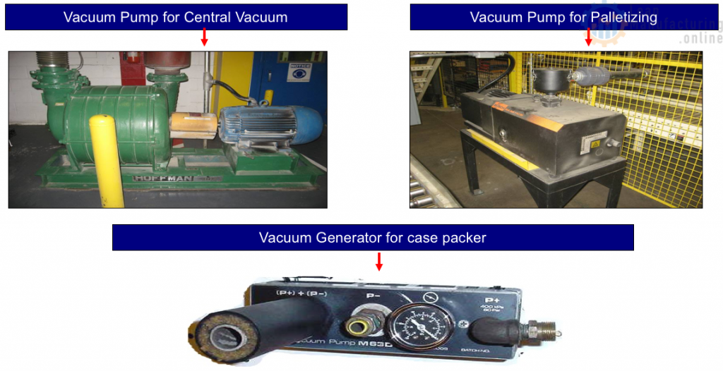
Some Vacuum Systems used in the factory are called Vacuum Generators or Venturi Systems.
The Vacuum System consists of an air source or air supply, a filter to clean the air going into the system, a pressure control valve or regulator to control the amount of air pressure, piping and fittings, a direction control valve or solenoid valve, which allows air to travel through the vacuum valve, and the vacuum valve. There is no oiler in this type of system. This system has an added filter in the vacuum or suction line. Trash particles and debris must be kept out of the vacuum generator. The Vacuum Cups (Suction Cups) are at the end of the line. The Vacuum Cups are what does the work. They come in all different sizes and shapes and are made from many materials.
Vacuum Generators generally operate off of low air pressure used to produce the vacuum. The size and type of generator will determine how much air is needed and the amount of hold it has. The air comes into one side of the valve and exits the other. In the middle is where the vacuum is generated. This is produced by air passing through chambers within the valve. This type of vacuum generator is expensive because of the compressed air used. Vacuum pumps are a lower-cost method of generating vacuum.
Vacuum Filters
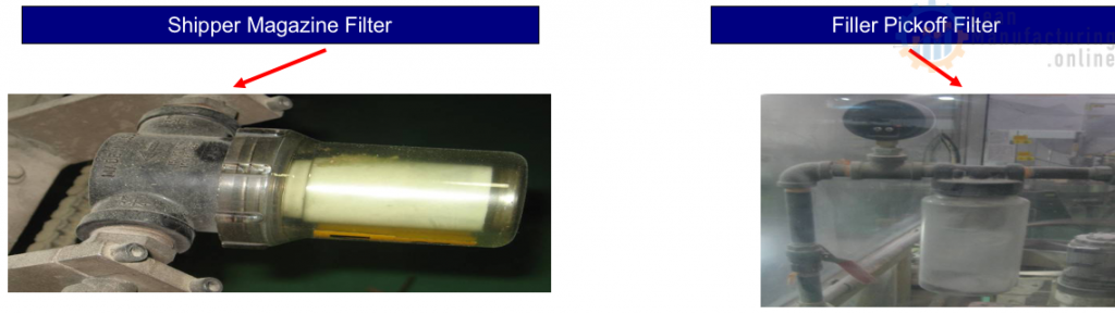
Care and Maintenance
Like the Pneumatic System, ensuring no leaks in a Vacuum System is important. It is necessary to check lines for holes and ensure the vacuum cups don’t have holes in them and are not torn or worn, which can result in vacuum loss. The filters must be kept clean so the vacuum or suction is not reduced. That’s why the pick-off filters and Brenton are so important to ensure reliability.


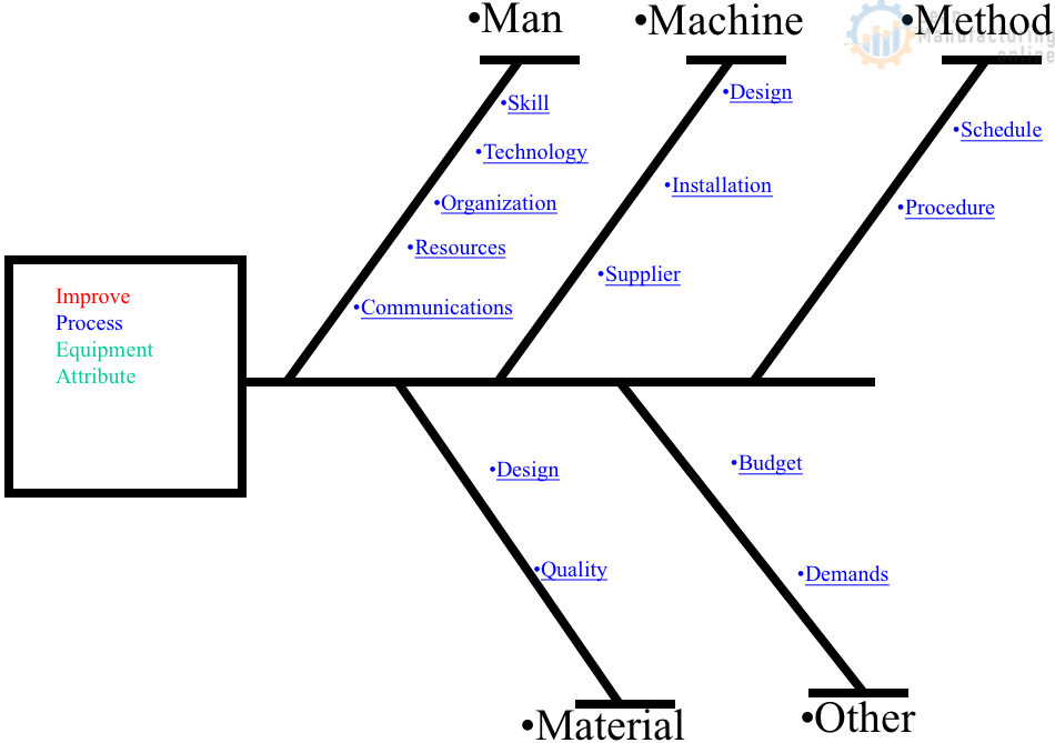
4M Analysis Process
The purpose of this procedure is to define the steps to do a 4M …