Understanding Geometric Dimensioning and Tolerancing (GD&T): The Ultimate Guide to Symbols, Rules, and Guidelines
Geometric Dimensioning and Tolerancing (GD&T) is the universal language of engineering design that ensures components fit and function as intended, regardless of where they are manufactured. It eliminates ambiguity by providing clear, standardized instructions for size, form, orientation, and location.
Why GD&T Matters
Producing thousands of parts that fail to assemble correctly can result in costly delays and rework. GD&T helps prevent these issues by communicating design intent with precision. This approach ensures consistent quality and reduces disputes during manufacturing and inspection.
Core GD&T Concepts You Must Know
- MMC (Maximum Material Condition): The feature contains the maximum amount of material—largest shaft or smallest hole within tolerance.
- LMC (Least Material Condition): The feature contains the least amount of material—smallest shaft or largest hole allowed by tolerance.
- RFS (Regardless of Feature Size): Tolerance applies at any size within the limit. No additional bonus tolerance allowed.
- Projected Tolerance Zone: Extends the tolerance zone beyond the surface for features like threaded holes to ensure proper fit.
- Free State: Indicates the part is inspected without external force applied.
GD&T Symbol Categories
GD&T uses a set of symbols divided into four primary categories:
1. Form Tolerances
- Straightness – Ensures a line or axis is perfectly straight.
- Flatness – Ensures a surface is perfectly flat.
- Circularity (Roundness) – All points on a circle are equidistant from the center.
- Cylindricity – Ensures a cylindrical feature is perfectly round and straight along its axis.
2. Orientation Tolerances
- Parallelism – Keeps a feature parallel to a datum plane.
- Perpendicularity – Maintains a 90° relationship to a datum plane or axis.
- Angularity – Keeps features at a specific angle other than 90°.
3. Profile Tolerances
- Profile of a Line – Controls variation along a line.
- Profile of a Surface – Controls an entire surface’s form.
4. Runout and Location
- Circular Runout – Controls circular elements during rotation.
- Total Runout – Controls entire surface runout during rotation.
- Position – Specifies the exact location of a feature.
- Concentricity – Aligns features to a common axis.
- Symmetry – Ensures equal distribution of features about a center plane.
Tolerance Zone Types
Tolerance zones can take the form of two parallel lines, two concentric circles, or two coaxial cylinders. These zones control allowable variation and maintain functional relationships.
Datums: The Reference Backbone
A datum is a reference point, line, or plane used for measurement. Most drawings reference primary, secondary, and tertiary datums for orientation and alignment of features.
Bonus Tolerance and Virtual Condition
When a feature departs from MMC toward LMC, bonus tolerance is added, improving manufacturability while maintaining functionality. The virtual condition represents the worst-case boundary for assembly fit even with tolerance accumulation.
Practical Tips for Applying GD&T
- Always specify datums clearly.
- Use position control for holes requiring precision alignment.
- Avoid over-dimensioning to reduce inspection complexity.
- Remember that RFS provides no bonus tolerance.
Why It Pays to Master GD&T
From design to inspection, GD&T reduces disputes, improves interchangeability, and cuts costs associated with defective parts. Whether you work in aerospace, automotive, or any precision-driven industry, understanding GD&T gives you a competitive edge.
What’s your biggest challenge with GD&T—reading drawings, applying tolerances, or explaining it to your team? Share your thoughts below!
Download hi-res PDF here


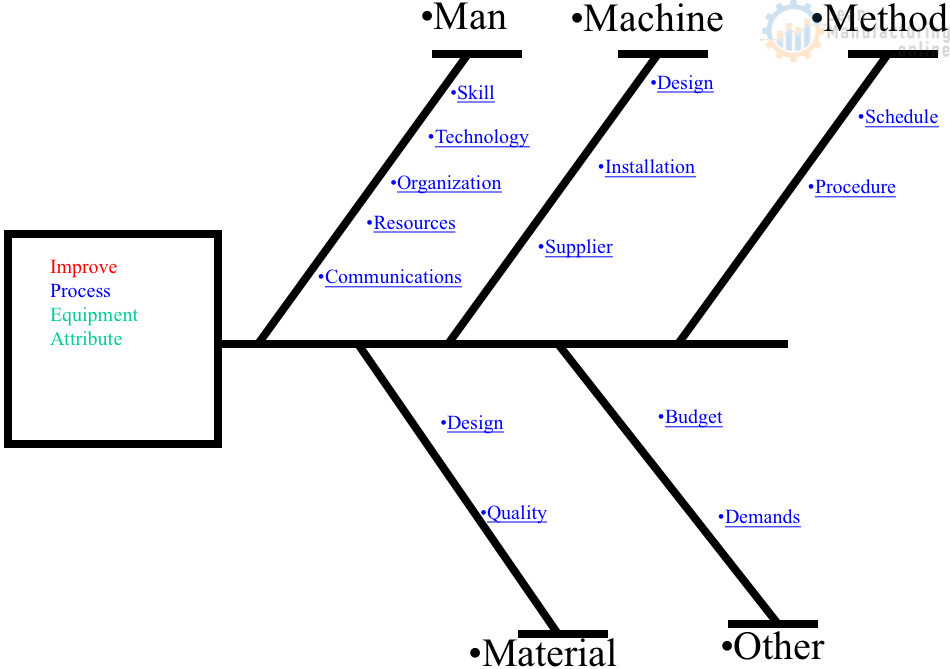
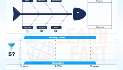
4M Analysis Process: Root Cause Guide for Manufacturing
Learn how to use 4M Analysis to find manufacturing root causes across People, Machine, Method, and Material with diagrams, examples, and checklist.