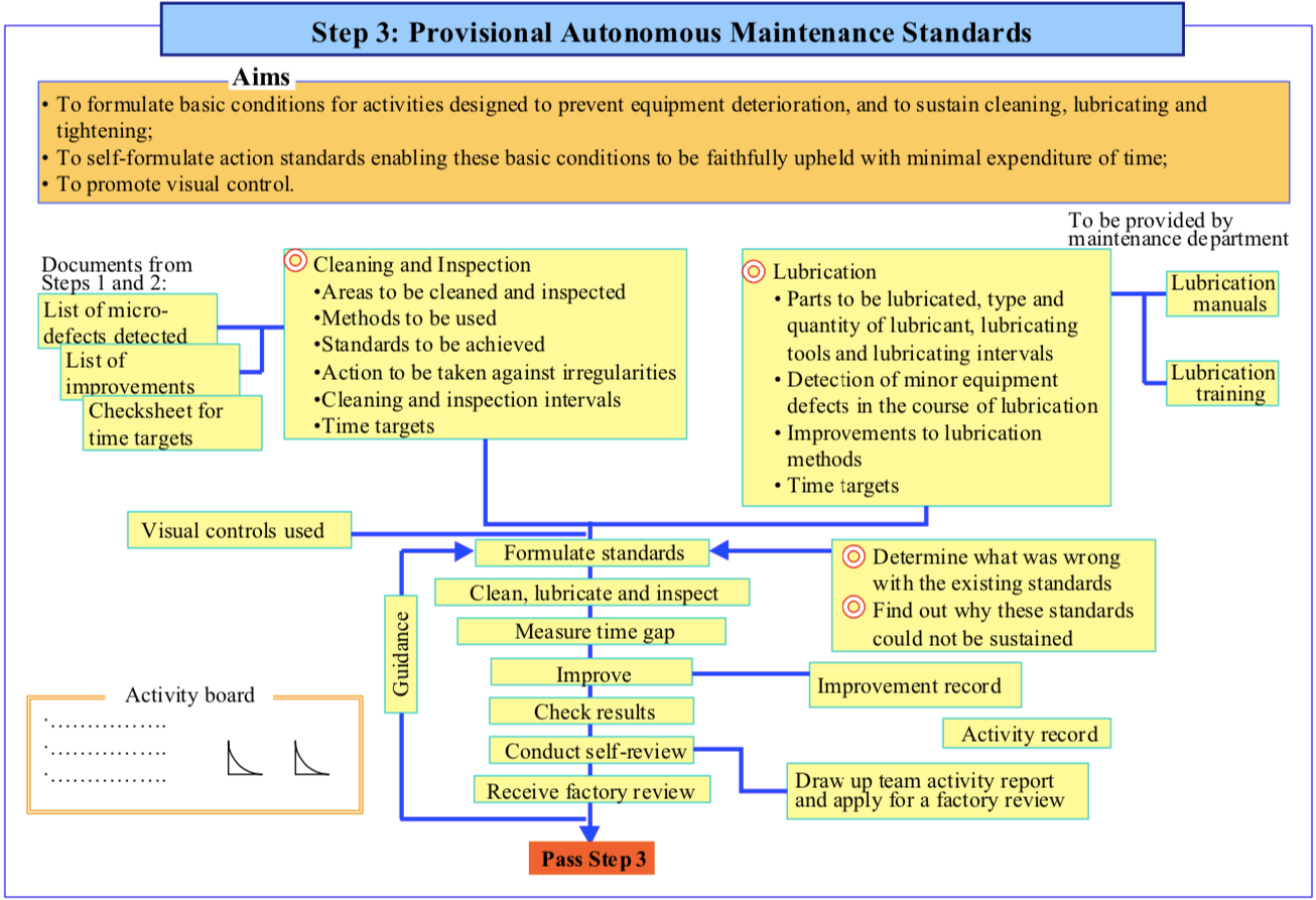
Aims
Based on the experience gained from AM Steps 1 and 2, the purpose of Step 3 is to
- Sustain the level of cleanliness achieved on passing Step 1; and
- Sustain the equipment improvements made in Step 2 to deal with contamination sources and hard-to-access areas
To do this, provisional standards for cleaning, checking, and lubricating must be formulated. Lubrication standards are drawn up by checking current lubrication practice and the state of lubrication of the equipment; identifying any problems, or areas that are hard to lubricate or check properly, and taking action to rectify these. The aim is to improve equipment reliability and maintainability by creating easy-to-follow standards.
Implementation
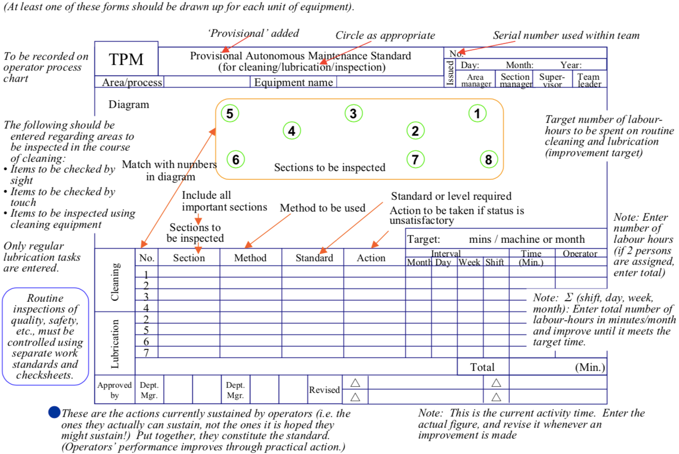
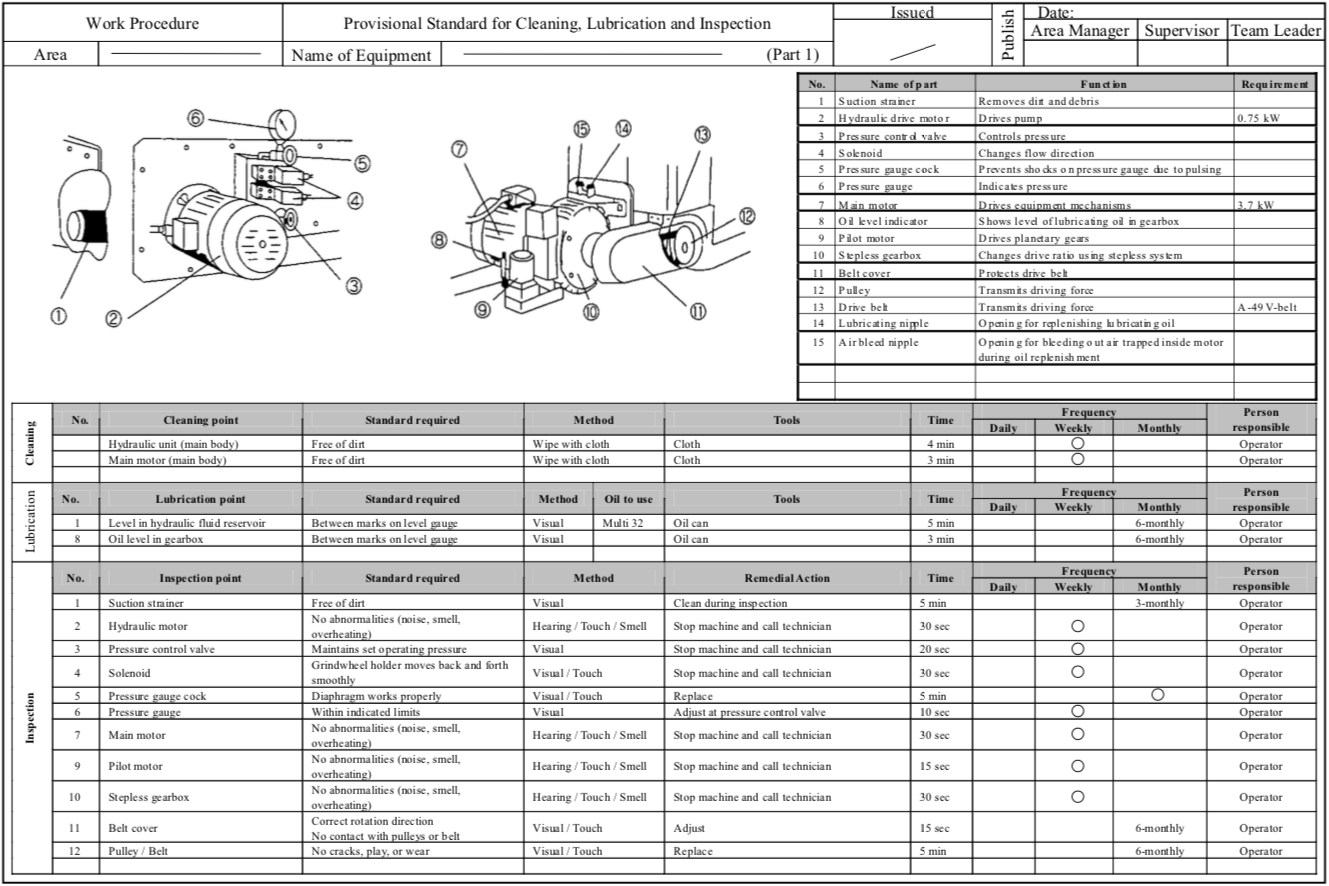
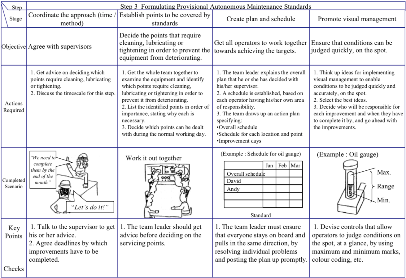
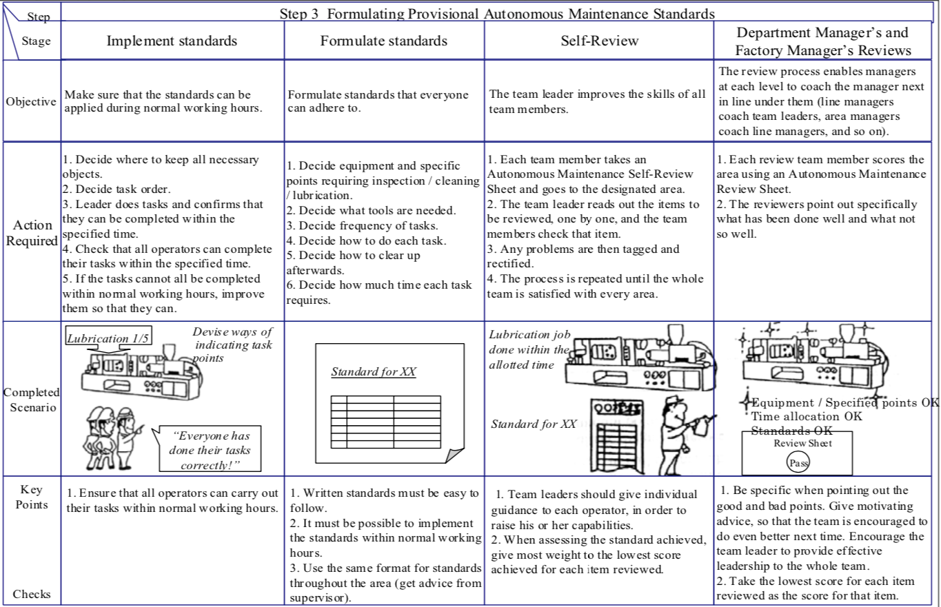
Step 3 is an important step in which operators use the experience they have acquired in Steps 1 and 2 to clarify what the ideal conditions for their equipment should be, and devise standards for the actions necessary to sustain those conditions (standards specifying the 5 Ws and 1 H, i.e. who is to do what, where, when, why and how). Figure “Template for Creating Provisional Autonomous Maintenance Standard” shows a typical template for creating a provisional standard, and Figure “A Typical Provisional Autonomous Maintenance Standard” shows a detailed example. The key points for this step are discussed below.
Key Points
(1) Why are standards not usually followed?
Companies often have a huge number of work standards and inspection standards, thought up by technical staff sitting in an office somewhere, that is not very relevant to the situation on the shop floor. The operators do not understand why they are necessary and are simply obliged by their managers to observe them. Before creating the provisional Autonomous Maintenance standards, a full inventory of existing standards must be taken to get a clear idea of the current situation.
(2) Establish standards that can be followed
The following points must be observed if standards are to be properly applied:
- The conditions to be sustained, and the methods to be followed, must be made explicit.
- The reasons why these conditions need to be sustained, and the negative consequences of not sustaining them, must be fully understood.
- The operators concerned must be given the capabilities needed to sustain the conditions.
- The prerequisites (such as sufficient time, etc.) for sustaining the conditions must be made available to the operators.
(3) Standards must be defined by those who have to observe them
To ensure that basic equipment conditions are reliably sustained, it is important to let those responsible for sustaining them define the necessary standards. This is in fact the first step towards self-management. To this end, the following requirements must be met:
- The operators must be taught why they need to set and follow standards.
- They must be helped to acquire the ability to formulate the standards themselves.
- They must actually be allowed to formulate the standards themselves.
If this is done, the standards prepared by the operators will be sustained. See Figure “Workflow for Step 3 (Provisional Autonomous Maintenance Standards)” for details.
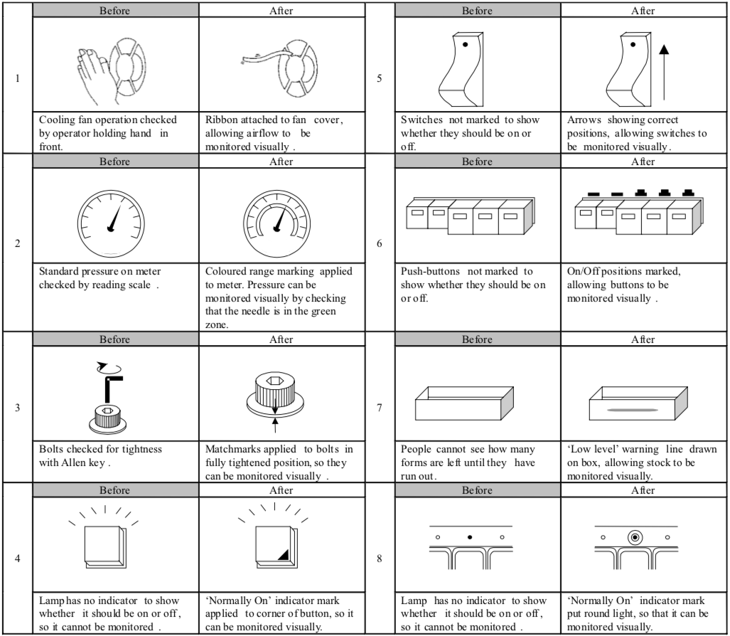
The difference between visual indicators and visual controls
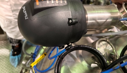
The diagrams below show the basic difference between visual indicators (Figure “Example of Visual Indicator”) and visual controls (Figure “Example of Visual Control”). This example relates to an FRL (filter, regulator, lubricator set) for a pneumatic device, and in particular, to its lubricator. The purpose of the lubricator is to hold the prescribed type of oil and supply it at the right time and in the right quantity to the downstream pneumatic device (e.g. a pneumatic cylinder or solenoid) where it is needed. The key function of the lubricator is not so much that of holding the oil, as making sure that it is supplied where and when required, in the right amounts.
In the example in Figure “Example of Visual Indicator”, the maximum and minimum levels are marked on the lubricator bowl, and the oil level is periodically checked to see if it still lies between these marks. It is easy to see whether or not the lubricator is holding the correct amount of oil, but this in itself will not prevent equipment failures or minor stops. This is because the level indicators cannot tell us whether or not the lubricator is fulfilling its real function, which is to supply the right amount of oil where and when needed.
To summarize:
- Visual indicators provide a guide for monitoring the item under observation.
- Visual controls make abnormalities in the actual function performed by the item under observation visible.
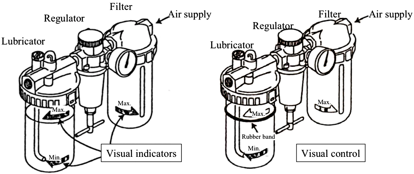
The figure above “Example of Visual Control” shows an example of how this problem can be solved, by placing a rubber band (O-ring) around the bowl in line with the oil level. If the level has dropped far enough below the rubber band the next time the level is checked, this demonstrates that the lubricator has been working properly.
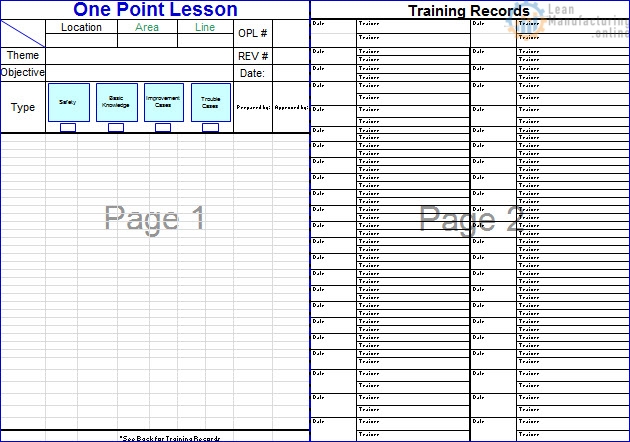
Autonomous Maintenance Step 3 Forms can be downloaded here
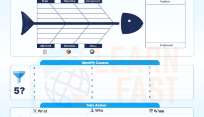


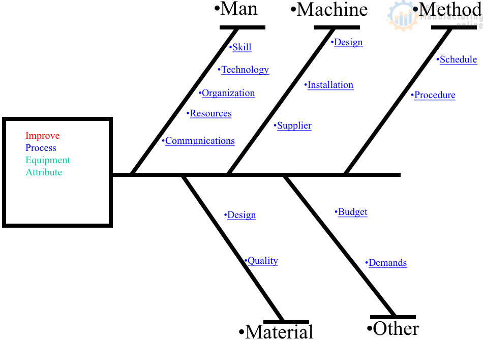
4M Analysis Process: Root Cause Guide for Manufacturing
Learn how to use 4M Analysis to find manufacturing root causes across People, Machine, Method, and Material with diagrams, examples, and checklist.