Drawings and sketches are universally used to communicate technical information. They are the graphic language used by everyone concerned with mechanical operations. They convey information, size, location, accuracy, etc.; and by their use, mechanisms ranging from the simple to the most complex can be graphically described. It is a universal language due to the general standardization of techniques throughout the world. For this reason, the language of drawings is understood in spite of native tongue and measurement differences. Drawings or sketches are the foundation of production interchangeability, enabling identical parts to be produced at widely separated locations. It is the guide for construction, assembly, installation, etc., of all forms, types, and kinds of objects.
Because it is such a vital and basic means of communication, it is essential that it be understood by the mechanic. He must be able to interpret or “read” drawings. He must be able to make simple sketches. This is very important because thoughts and ideas are almost impossible to express with words alone—but frequently can be illustrated by a simple sketch.
The term drawing usually refers to a graphic illustration made by a draftsman with the aid of scales, instruments, etc. When made freehand with pencil or pen, without mechanical devices, they are usually referred to as sketches. In either case, basic principles and concepts as well as generally accepted conventions are followed.
The word blueprint is loosely used to describe many different types of drawing reproductions. It originally described a specific type that had white lines on a blue background. The blueprint process of drawing reproduction is one of the oldest, and still widely used, methods of duplicating drawings. In reproducing drawings by this method, the blueprint is made on paper coated with a light-sensitive material called an emulsion. A drawing made on special paper that will allow passage of light, or a transparent tracing of a drawing, is placed on the paper and exposed to strong light. The lines on the drawing or tracing hold back the light and leave an impression on the blueprint paper. After exposure to light, the paper is passed through a developer and washed with water. Except for shrinkage, the blueprint is an exact duplicate of the original drawing. This process is commonly referred to as a “wet process.” Also derived from the original blueprint process is the term “blueprint reading.” This term is now applied to the general interpretation or reading of all forms of drawing, sketches, and prints or drawing duplicates.
Another process that has become widely used in recent years, probably because it is a so-called dry process, is ammonia development of prints. This is also a contact method of reproduction and results in a print with a white background. The lines are usually blue or black, although other color lines may also be produced. In this process the coated paper, after exposure to light, is developed by exposure to ammonia fumes.
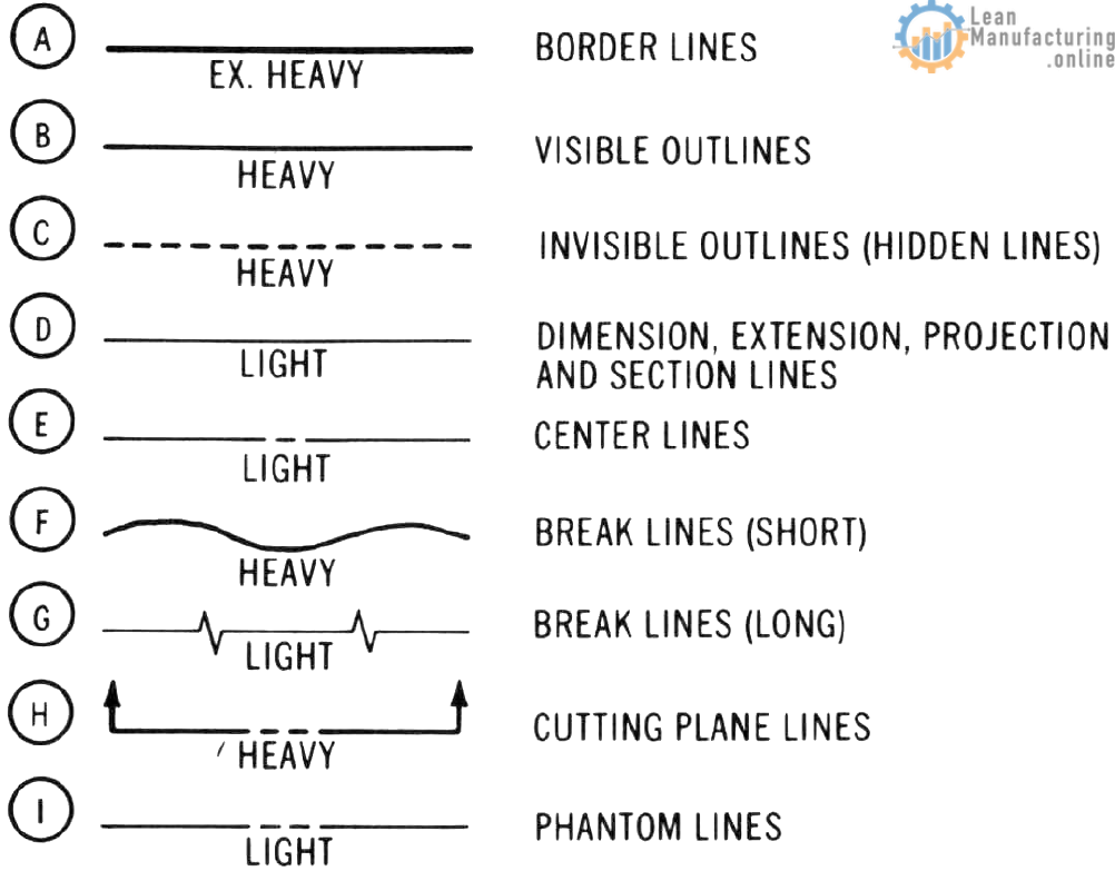
Lines
Drawings are made up of a combination of lines of different lengths and intensity. These define the shape, size, and details of an object. It is possible, through the correct use of lines, to graphically describe an object so that it can be accurately visualized by any person having a basic understanding of drawing principles. Since lines are the basis for all drawings or sketches, a listing of lines used for various purposes may be called an alphabet of lines. Figure “Alphabet of lines” and Figure “Use of lines” illustrate the use of these lines.

Projections
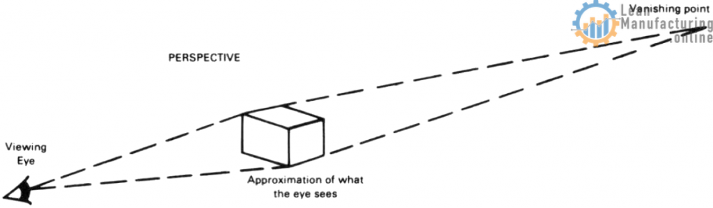
Mechanical drawings and sketches are not a true representation of what the human eye actually sees. What is seen by the eye is most nearly represented by what are called “perspective drawings,” or sketches. The portion closest to the observer is the largest, while the parts farthest away are the smallest. Lines and surfaces become smaller and closer together as distance from the eye increases, seeming to disappear at a point on an imaginary horizon called a “vanishing point.” Perspective drawing or sketching is pictorial in nature, often influenced by artistic talent and not readily lending itself to mechanical methods and drawing practices.
The word projection is used when describing the various systems of mechanical drawing. It refers to the extension (projection), to a plane or sheet of paper, of what is seen by the eye as it views the object. The most widely used system of drawing is called orthographic projection. The word orthographic may seem a little overpowering. For purposes of making it more understandable, the word can be divided into two parts, ortho and graphic. The first part, ortho, is derived from the Greek orthos and means “straight.” The second part, graphic, is from the Greek graphein, meaning “to write, diagram, or picture.” Graphic is usually defined as meaning lifelike, vivid, or pictorial. Orthographic, then, simply means that a picture is made by projecting the lines of sight in a straight line or parallel and at right angles to the surface being viewed.
Of course the eye does not do this when it views an object from a single point. As previously stated, drawings and sketches are not true representations of what the human eye actually sees. To project the lines representing the edges of an object parallel, it must be assumed that the eye is seeing the edge from a point where the line is projected. This concept of orthographic sight projection is difficult for many persons to grasp. To visualize orthographic projection the eye should be considered as moving in a pattern that exactly matches the shape of the object.
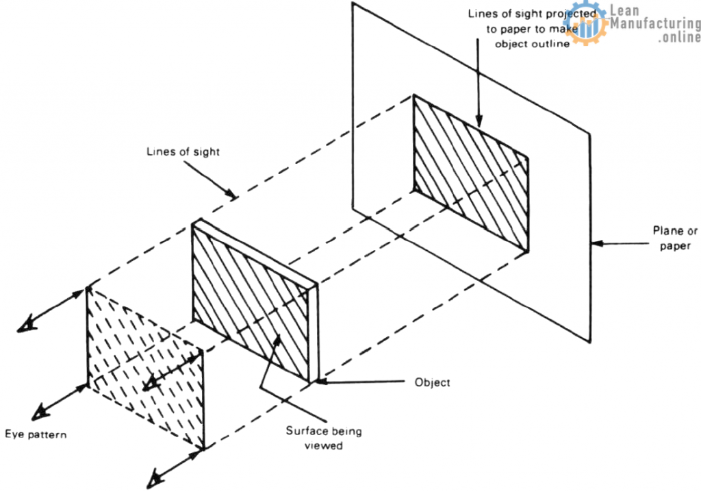
If the eye were to move in this pattern and the edges of the object were to be projected to the surface of the plane or paper, a true representation of the outline of the object could be drawn on the paper. Such a drawing represents only the outline of the surface of the object. Additional drawings from other viewing points would be necessary to show the various features of the object, such as thickness variations and other surface shapes. These additional drawings, as well as the original, are called “views” (each taken from a specific viewing position). Several such drawings, or views, are required to show various features of an object clearly. Therefore, what is commonly called a “drawing” may b e made up of several related drawings, usually referred to as “views.” Standardized principles and practices govern the positioning of these views in relation to one another on a drawing. To show size, shape, and location of the various parts of an object, a number of views are necessary. In orthographic projection, each view shows the part of the object as it is seen by looking directly at the surface. Each view therefore represents the true shape and size of the surface of the object being viewed. Probably the most widely used combination of views is that of the top, front, and right side. They are arranged so that each view represents the surface adjacent to it, as shown in Figure “Three-view drawing.”

Arrangement of Views
Several methods of selecting or obtaining the views to be shown on a drawing are used. Probably the most widely used method is the direct or natural method. In this way, the front view may be thought of as a view obtained by looking at the object from a position directly in front of it; the top view by looking at it from above; and the side views by looking at it from the sides (right or left).
The views are arranged on the drawing in the same manner in which they are viewed. The top view is drawn above and vertically in line with the front view. The side views are at the side of the front view and horizontally in line, to the right or left as the case may be.
Usually the front view shows what is normally considered the front of the object in its natural position. However, the views may be selected to give the best description of the object’s shape. In this case, the front view might have no relationship with the actual front position of the part as it fits into an assembled position with other components. See Figure “Arrangement of views.”

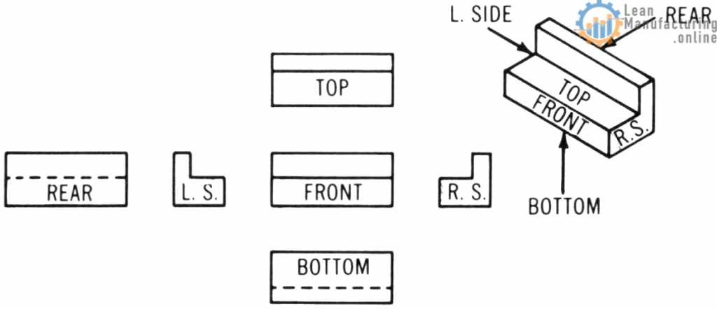
The names of the six (6) principle drawing views indicate the viewing positions. They are the front, top, right side, left side, bottom, and rear views. Since the main purpose is to furnish sufficient information to build, assemble, or install an object, only those views required to accomplish this purpose are necessary. To a large degree, this is determined by how simple or complex the part may be. See Figure “The six principal views.”
Two-View Drawings
Simple symmetrical flat objects and cylindrical parts, such as shafts and sleeves, can be adequately shown with two views. Usually, the front view can be shown in combination with either a right or left side view, or a top or bottom view. See Figure “Two-view drawing.” The selection of views is usually made on the basis of the

combination that shows the object to best advantage. When a choice of combinations will do this, the object should be shown in its natural position in the front view.
One-View Drawings
Some parts that are uniform in shape may be adequately described with a one-view drawing. This is done with cylindrical parts by using the letter “D” to indicate the dimension given is a diameter. A further indication that the part is cylindrical is the use of the center line, which indicates that the part is symmetrical. This is shown in Figure “One-view cylinder drawing”.
One-view drawings may also be used to show flat parts. Through the use of simple notes to supplement the drawing dimensions, all the information necessary to accurately describe the part can be furnished, as illustrated in Figure “One-view flat-object drawing”.


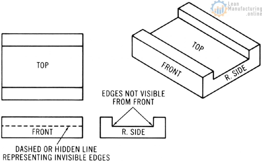
Hidden Lines
When viewing the surfaces of an object, many of the edges and intersections in the object are not visible. To be complete, a drawing must include lines which represent these edges and intersections. Lines made up of a series of small dashes, called invisible edge or hidden lines, are used for this purpose in Figure “Hidden lines.”
Auxiliary Views
When the surfaces of an object are at right angles to one another, regular views are adequate for their representation. However, when one or more are inclined and slant away from either the horizontal or vertical plane, regular views will not show the true shape of the inclined surface. To show the true shape, an auxiliary view is used. In an auxiliary view, the slanted surface is projected to a plane which is parallel to it. Shapes that would appear in distorted form in the regular view appear in their shape and size in the auxiliary view. Usually only the inclined surface is shown in the auxiliary view, presented in its true shape and size as shown in Figure “Auxiliary view.”

To be continued…

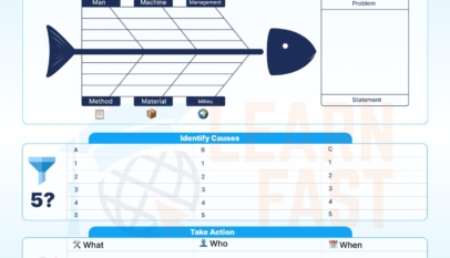


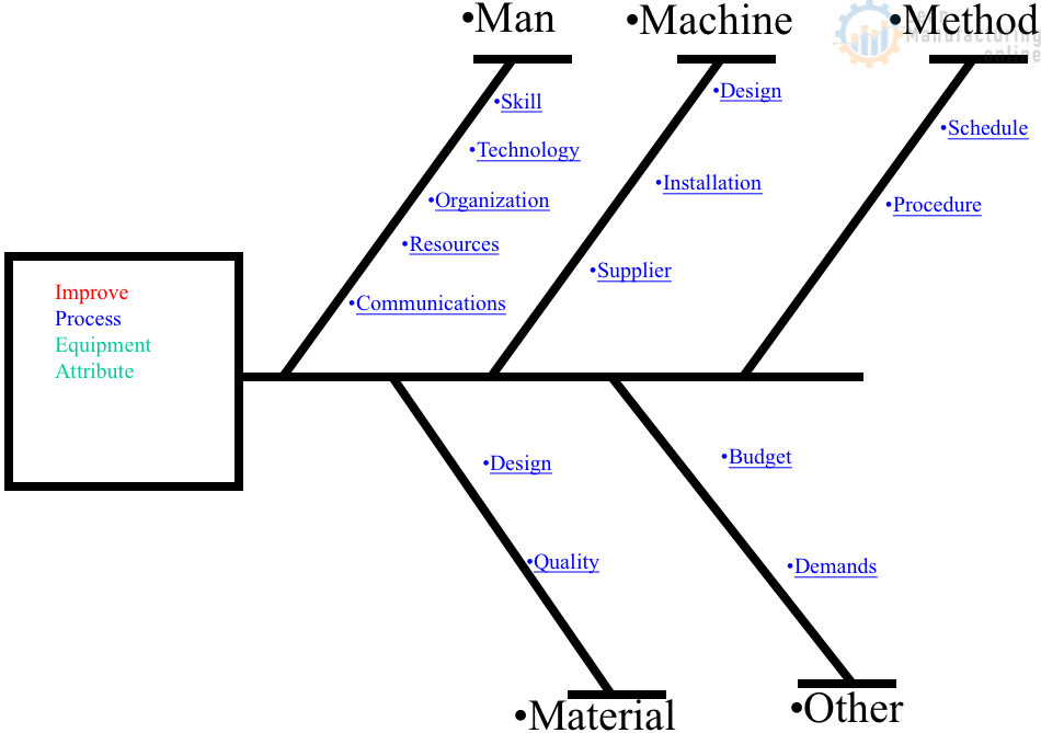
4M Analysis Process: Root Cause Guide for Manufacturing
Learn how to use 4M Analysis to find manufacturing root causes across People, Machine, Method, and Material with diagrams, examples, and checklist.

Hi,
I am a big fan and reader of your content about WCM . I would like to know about new features and presentation about world class manufacturing can you give me suitable data about that because this is they way to my learning source of your site. thanks
Regard.
M . Hafeez
Hi Muhammad,
Thanks for the comment; please specify what exactly you are looking for.