Step 1: Clarify the phenomenon
A phenomenon is an observable event or occurrence, and ‘clarifying the phenomenon’ means identifying what is causing the problem by careful observation of the facts. If the phenomenon (what is actually happening) can be pinpointed, the problem is halfway to being solved. Conversely, a P-M Analysis conducted on a phenomenon that has not been accurately identified will miss the mark and be merely a waste of time.
The important thing when observing the phenomenon is to actually see it for yourself, without relying on what other people have told you. The problem should be carefully observed, and what actually happens, the way in which it happens, its location on the machine, any differences between one machine and similar ones, and other factors should be examined to see if exactly the same phenomenon is happening every time, or whether there are any differences. Analyzing the phenomenon in this way is called stratifying. The key point is to analyze the problem carefully and objectively, without jumping to conclusions. Serious errors can result from making judgements without having sufficiently stratified the phenomenon.
It may be possible to observe a phenomenon as it is actually happening (catching the criminal in the act, so to speak). Often, however, only the end result can be seen (like turning up at the scene after the crime has been committed). The former is often possible with minor stops, while the latter is more common in the case of breakdowns and quality defects.
When a phenomenon happens very rapidly, it is extremely effective to film it with a high-speed video camera and then watch the video in slow motion to see exactly what is taking place. This is a good technique to use with minor stops, which are mainly caused by products catching or jamming somewhere in a machine, and with some quality defects.
Even if the phenomenon cannot be observed as it is happening, there is usually sufficient evidence left behind to formulate a hypothesis about its causes – if a machine has broken down, for example, the broken part will always show signs of having received energy. It is important to infer from such signs what kind of energy was applied to the part, and from what direction, to cause it to break. The broken surfaces should be examined under a magnifying glass or microscope to determine their condition and structure, and the part should be kept until the cause of the problem has been tracked down.
The causes of quality problems can also sometimes be inferred by examining the defective product under a microscope or with measuring instruments, particularly if the problem relates to the product’s shape. In other cases, it is important to observe the phenomenon from the 5W1H standpoint, trying to identify whether its occurrence depends on the machine or lot, the operator, the season, the day of the week, the time of day (first thing in the morning, just after a changeover, etc.) and so on, and whether there are any identifiable cyclic or time-based patterns in the way it happens.
The next block summarizes what needs to be done in order to clarify the phenomenon.
Clarifying the phenomenon means understanding the phenomenon precisely, observing exactly how it occurs, and knowing what patterns it exhibits. To stratify it effectively (i.e. to determine what factors its occurrence depends on, and how its occurrence depends on those factors), the following key actions should be taken:
- Observe the facts carefully, using the ‘3 Actuals’ approach (actual location, actual objects and actual facts).
- Use the 5W1H approach (What? Where? When? Which? Who? How?) to stratify the phenomenon until it can be stratified no more.
- Compare the normal situation (or good product) with the abnormal situation (or defective product) and identify all significant differences.
Step 2: Perform a physical analysis of the phenomenon
All phenomena can be explained in terms of physical principles and parameters. Physically analyzing a phenomenon means examining it in order to establish the physical principles behind it. For example, if an object has become scratched, it must have brushed against or collided with a harder object. Thus, if a product keeps getting scratched during a manufacturing process, looking for places where it could come into contact with a harder object will indicate which parts of the machine need to be investigated and make it easier to identify the causes. This step is crucial for the following reasons:
- A sound physical analysis of the phenomenon will reveal all the relevant potential causes.
- Since it is logical and systematic, it ensures that no potential causes are overlooked.
- It prevents conclusions being drawn on the basis of intuition and guesswork.
Before conducting a physical analysis, however, there are two important sub-steps that must be completed – understand the mechanism, and identify the principles and parameters. These will now be described.
(1) Understand the Mechanism
The key to success when analyzing the potential causes of an undesirable phenomenon is to start by learning about the equipment where the phenomenon occurs – how it works, and how it is constructed. If this is well understood, the mechanism by which the phenomenon occurs will naturally become apparent. Despite this, however, many people jump straight into investigating the causes of problems without first going through this step.
To find out how the equipment does its job, and how it is put together, start by doing a three-dimensional diagram like that shown in Figure “Mechanism Diagram of Small Turntable Winder”. Mark out the equipment’s functional units with dotted lines, name the units and write a brief description of what each does. Next, make a list of all the individual components each unit is assembled from, with their names and functions. Doing this should make it clear that every component has a role to play and none is superfluous. It also becomes apparent what kinds of problems would happen if any of the components were not maintained to the required degree of precision – useful knowledge for establishing zero-defect conditions in Quality Maintenance. It has been demonstrated time and again that a sound knowledge of the structure and functions of the equipment and its component parts makes the subsequent investigation of the causes of problems far quicker, more accurate and more reliable.
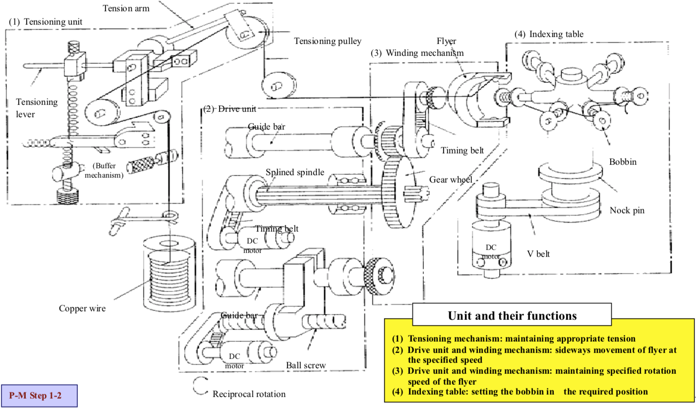
A word of warning – do not confuse a sketch of the outside of a machine with the three-dimensional diagram required here. The drawing required here – called a ‘mechanism diagram’ – should clearly show how the parts fit together, how the motive force is transmitted, and how the machine actually does what it is supposed to. It is also essential to hand-draw the diagram yourself. Photographs or copies of manufacturers’ drawings should never be used instead. Remember that the point is not to produce a drawing but to use the act of drawing as a highly effective means of learning all about the way the equipment is constructed and how it works. Seven items for understanding the mechanism list the key points to bear in mind at this stage:
- Read the manual at least five times to be sure you understand it.
- Understand the mechanisms used to transmit power, actuate the machine and process the work. Work out how the parts fit together.
- Draw a diagram including all of the units and components relevant to the problem.
- Always draw a three-dimensional (perspective) diagram, not a two-dimensional one.
- Draw the diagram freehand while standing in front of the equipment.
- Check the hydraulic circuit diagrams, electrical circuit diagrams and cycle diagrams as well.
- Check the processing conditions, setup conditions, operating procedures, etc.
(2) Understand the principles and parameters
Once the mechanism and construction of the equipment have been understood, the next important step is to sort out the principles and parameters, as defined in the principles and parameters below. All too often, people operate and maintain machines without understanding the principles by which those machines operate or the parameters under which they must be operated, but this makes it almost impossible to understand the mechanisms by which quality defects and other problems are produced. It is essential to understand the principles and parameters in order to conduct a physical analysis and establish the contributing conditions.
- Principles
- Principles include principles of processing, principles of operation, principles of measurement and principles of control.
- Principles of processing are the basic laws by which the shape and nature of physical objects and materials are changed.
- For quality defects, analyse principles of processing, principles of measurement and principles of control. For minor stops, focus on principles of operation and principles of control.
- Parameters Parameters can be thought of as the basic rules that must be observed in order for the principles to work.
In the majority of cases, principles correspond to the physical analysis part of a P-M Analysis, while parameters correspond to the contributing conditions.
To illustrate what is meant by principles and parameters, let us consider an ordinary battery-powered torch. The principle by which the torch lights up could be described as An electric current is made to pass through a resistance wire, heating it up to 1,000°C, the temperature at which it emits light (see Figure “Principles and Parameters of a Torch”).
The parameters (conditions) that must be in place in order for this principle to operate are:
- The battery produces a certain minimum EMF,
- There is adequate contact between the battery and the bulb’s filament (i.e. no breaks in the circuit),
- The bulb is in good condition and of the specified rating.
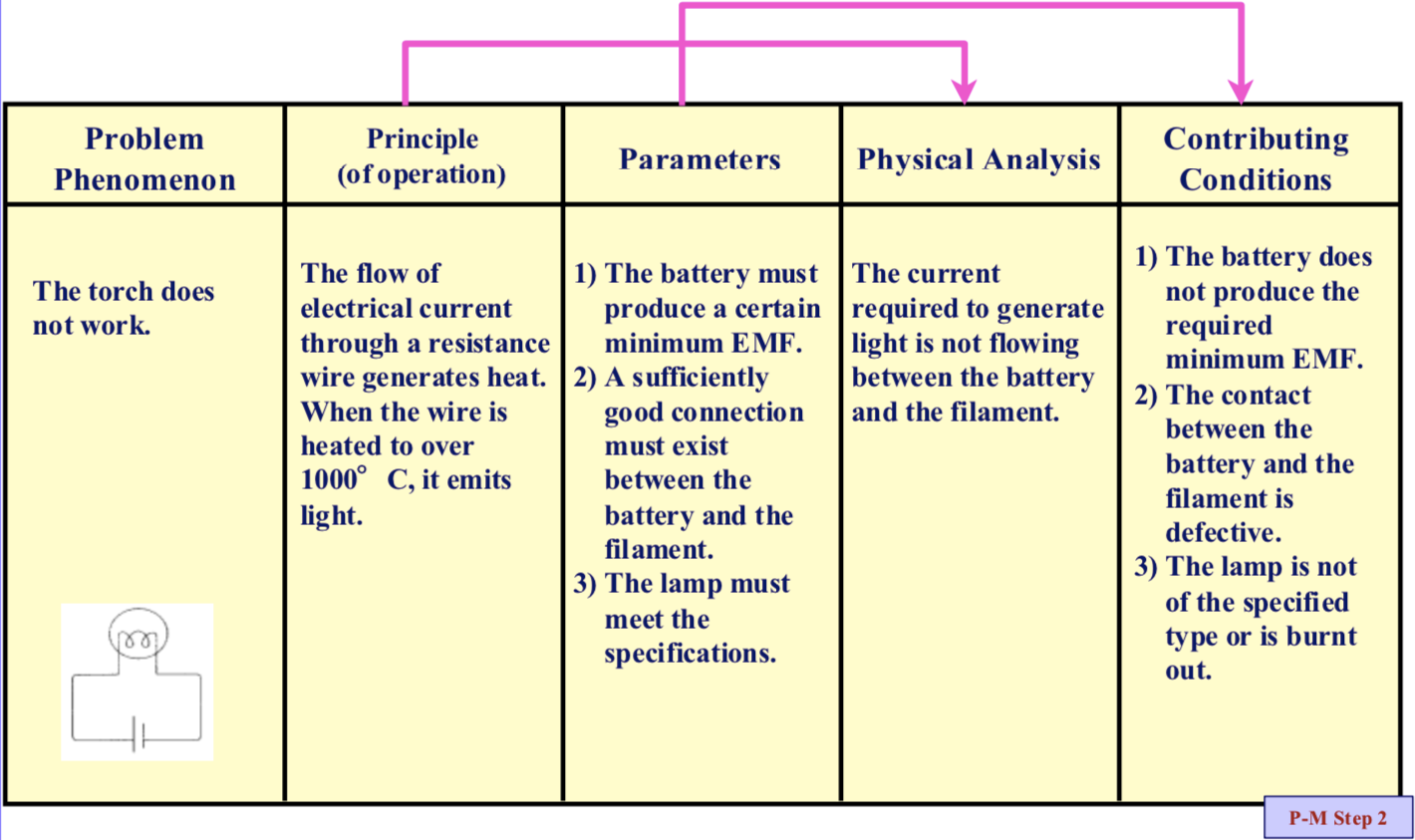
If the torch failed to light when switched on, the physical analysis of the phenomenon would be that Not enough electric current to cause light emission flowed between the battery and the bulb, and the contributing conditions (any condition that would give rise to the situation described by the physical analysis) would be the failure of the parameters described earlier.
Parameters can be thought of as the minimum conditions necessary in order for the principle to operate correctly. They can most easily be identified as the minimum conditions that must exist for each of the functional units of the system to do its job. In the case of a torch, for example, the functional units are the battery, the circuit wire and the bulb.
(3) Conduct a physical analysis
Conducting a physical analysis means logically establishing how an event would take place. It consists of elucidating the mechanism by which the phenomenon occurs, via a change in a particular physical quantity, based on the principles and parameters already identified. It may in fact be easier to think of it as analyzing the physical quantity involved. To help explain what it means, let us take a certain type of machining operation as an example.
To process an object or material is to change its shape or nature, which requires the application of some form of energy to the object or material. In fact, the processing is no more than the application of a defined amount of energy at a defined position.
Incidentally, the amount of energy applied is given by the following equation:
Amount of energy applied = rate of application of energy (force, heat, electric current, etc.) x time
In a machining operation, energy is applied to a workpiece through the point of contact between the workpiece and a cutting tool. This point of contact is known as the processing point. This means that there would be no possibility of a defective product being produced if the position of the processing point and the amount of energy being supplied to the workpiece via the cutting tool remained correct. A defective product is always the result of a deviation in the position of the processing point or the amount of energy from what it should be.
Therefore, to consistently make good products, these two things (the position of the processing point and the amount of energy supplied) must be kept correct at all times. The physical analysis of a problem phenomenon is a description of how this is not happening.
An appropriate physical analysis of a phenomenon can usually be arrived at by following the procedure shown below.
- Locate the processing point (the point at which energy is transferred).
- Sketch the processing point.
- Clarify which object is giving the energy (A) and which object is receiving the energy and thereby changing its shape and/or characteristics (B).
- Clarify the physical, quantitative parameter (C) that governs the change in shape and/or characteristics. Physical parameters include those related to position of the processing point, such as distance and angle, and those related to the quantity of energy, such as force, speed, acceleration, temperature, electrical current, voltage and time.
- Clarify the change (D) in the physical parameter.
- Express this relationship in writing, typically in the form ‘A and B cause C to change D’.
- If the occurrence of the phenomenon can be expressed in terms of an equation or formula (e.g. a reaction formula), this itself can be used as the physical analysis.
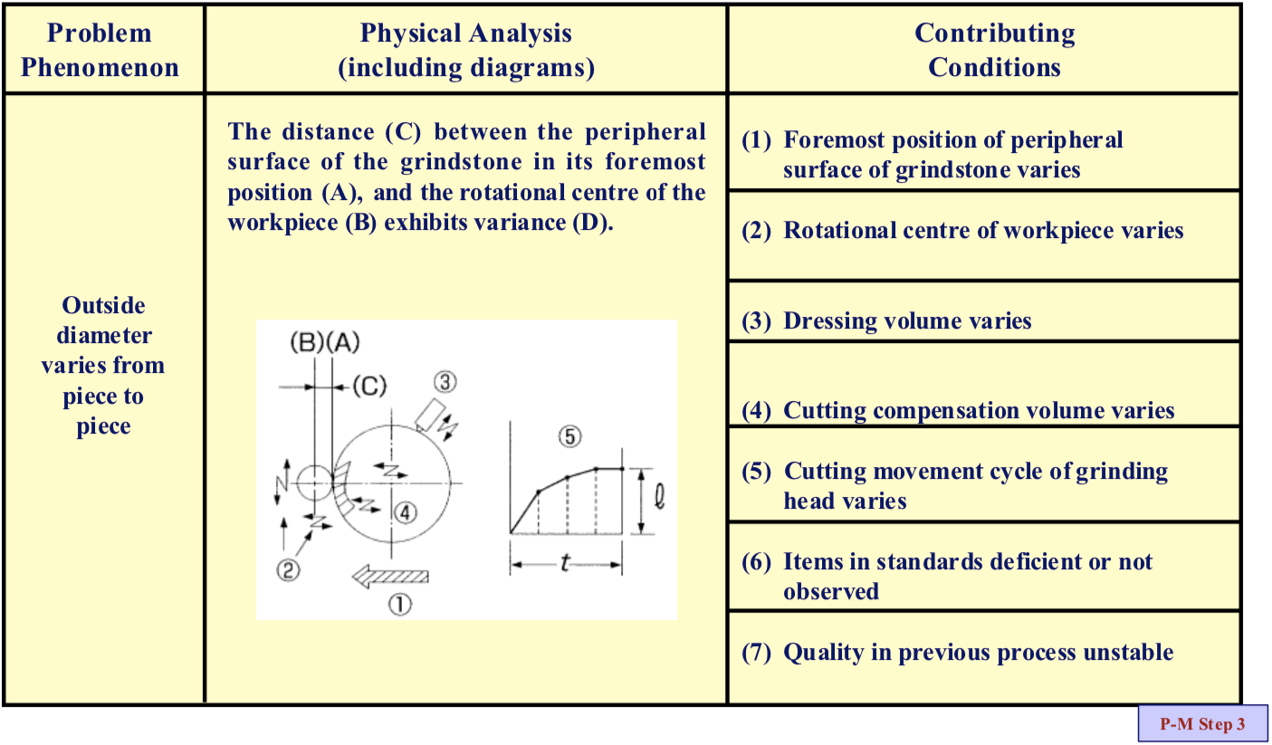
Let us explain this in more detail by looking at a real-life example, that of a metal cylinder being machined to size with a precision grinding wheel (see Figure “The Thinking behind Physical Analysis”), where the undesirable phenomenon is that the finished outside diameter of the cylinder varies. The object imparting the energy (A) is the grindstone, and the object that receives the energy and changes shape is the cylinder (B). The principle of operation of a cylindrical grinding wheel could be expressed as ‘Abrasive grains (N.B. these are equivalent to cutting tools) in a grindstone rotating at high speed bite into the surface of a revolving workpiece, shaving off its surface in the form of filings. By cutting continuously into the workpiece, the grindstone finishes it to the specified shape and dimensions.
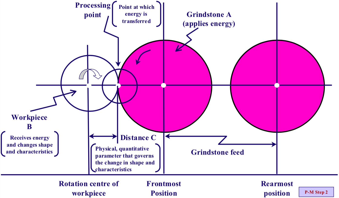
In an actual grinding operation, the grindstone works in cycles, first moving forward (while grinding the workpiece) to a preset foremost position, then halting briefly, then retreating to its starting position. This means that the physical parameter (C) that determines the outside diameter of the cylinder, as the grindstone cuts, is the distance between the surface of the grindstone and the centre of rotation of the cylinder.
The physical analysis of the problem phenomenon (that the outside diameter of the cylinder varies) can therefore be expressed as, “The distance (C) between the surface of the grindstone (A) in its foremost position and the rotational centre of the cylinder (B) exhibits variance (D)”.
It should be noted here that each distinct phenomenon can only have one physical analysis. If you see more than one physical analysis for a phenomenon, it means that the phenomenon has not been stratified in sufficient detail and that Step 1 (Clarify the phenomenon) needs to be repeated. Also, if it is difficult to express the physical analysis in words, a diagram, mathematical formula, reaction equation, etc. can be used instead.
Step 3: Identify the phenomenon contributing conditions
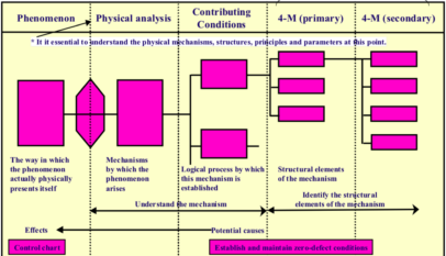
In this step, we use the underlying physical principles and parameters to identify all the conditions (the “contributing conditions”) that will inevitably produce the phenomenon if they are present. The key point here is to identify all of these conditions. The phenomenon is physically analyzed, the mechanism by which it occurs is elucidated, the conditions that logically must give rise to it are identified, and all conceivable situations in which it could arise are logically worked out, without relying on experience, subjective judgement or gut feelings.
In conventional cause analysis, only some of the many contributing conditions are taken into account. Causes are sought for them, and corrective action is taken, but the losses often do not decline, because other relevant conditions have been ignored. It is important to do a comprehensive analysis that does not exclude anything just because it is thought unlikely to have much bearing on the problem.
It was explained earlier that parameters are the minimum conditions necessary in order for the principle to operate correctly, and that they are the minimum conditions that must exist for each of the functional units of the system to do its job. In many cases, the contributing conditions that give rise to a particular phenomenon consist of insufficient accuracy in the maintenance of these parameters.
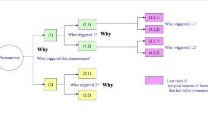
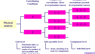
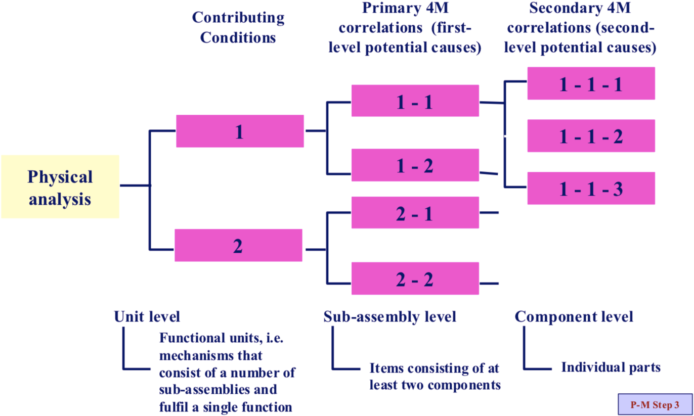
As a guideline, when using P-M Analysis to unravel the chain of causes behind a phenomenon, contributing conditions can be thought of as operating at the level of the system’s functional units (assemblies that perform a single defined function), primary 4- M correlations as operating at the level of sub-assemblies (smaller assemblies that compose the functional units) and secondary 4-M correlations as operating at the level of individual components (see Figure “Guidelines for Developing Structure of Potential Causes”).
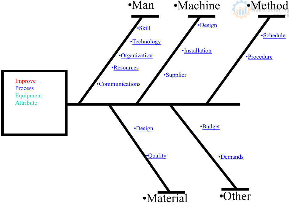
Also, when listing the contributing conditions, the situation should be considered in the light of each of the 4-Ms (machines, methods, men/women, materials). Start by considering the mechanical precision of the equipment, then go on to consider methods (inadequate processing conditions, standards, etc.), people (not observing the standards) and materials (quality from the previous process). P-M Step 3 procedure shown below in more detail:
Equipment
1) Look at what functional units the mechanism is composed of (these should have been identified on the mechanism diagram).
2) List each functional unit with a description of its function (these should also have been understood when doing the mechanism diagram).
3) Taking each unit in turn, consider whether, if it failed to do its job properly, the physical parameter specified in the physical analysis would be affected.
4) Treat each of the units identified in Step 3 (the ones that would affect the physical parameter if they did not do their job properly) as a contributing condition. Describe in writing the way in which each unit has to not work properly in order for the physical parameter to be affected.
Standards and Personnel
5) Consider whether, if the processing conditions and standards were deficient or not
strict enough, or the people supposed to observe them did not do so, the physical parameter specified in the physical analysis would be affected. Then express the situation in writing as in item 4 above.
Materials
6) Consider whether, if there were something wrong with the materials, or the quality in an upstream process was poor, the physical parameter specified in the physical analysis would be affected. Then express the situation in writing as in item 4 above.
Let us continue with the grinding wheel example to illustrate in more concrete terms how to identify the contributing conditions. As we have seen, the physical analysis of the phenomenon is that “The distance (C) between the surface of the grindstone (A) in its foremost position and the rotational centre of the cylinder (B) exhibits variance (D)” (see Figure “Step 3: How to Identify the Contributing Conditions”). This sentence contains two conditions: ‘the surface of the grindstone (A) at its foremost position’, and ‘the centre of rotation of the cylinder (B)’. These two conditions can be taken as the contributing conditions just as they are. All we need to do is to express in words what must happen to them in order to produce the variation in the physical quantity identified in the physical analysis (‘the distance C exhibits variance’).
Quite simply, the two contributing conditions are:
(1) The surface of the grindstone (A) at its foremost position varies
(2) The centre of rotation of the cylinder (B) varies
Next, we look at the other functional units that compose the grinding wheel to see whether any change in their working would produce a change in the physical quantity. There are in fact two more functional units, the grindstone dressing unit and the cutting compensation feed unit, and examination shows that each is associated with one of the following two contributing conditions:
(3) The dressing volume varies (the dressing unit)
(4) The cutting compensation volume varies (the cutting compensation feed unit).
All four of these contributing conditions relate to equipment precision. However, there are also two others relating to methods:
(5) The cutting movement cycle of the grinding head varies
(6) Items in standards are deficient or not observed
And one other relating to materials:
(7) The quality in the previous process is unstable.
The next 4 steps summarise the key points for identifying contributing conditions.
1) First, take the two conditions identified in the physical analysis (the object that gives energy and the object that receives energy) as contributing conditions.
2) Then look at the remaining functional units to see whether changes in their functioning could produce a change in the physical parameter.
3) Review the processing conditions, work standards etc. to see if any are deficient or not being followed.
4) Examine the materials and the quality of previous processes.
Two common patterns by which contributing conditions arise.
Pattern 1: When the physical analysis takes the form, “Condition AB does Z”
1) Separate A and B
- Physical quantity A does X
- Physical quantity B does Y
2) Split up the physical quantities
Example: Friction force = friction coefficient x applied pressure x surface area – The friction coefficient between A and B is N1.
- The pressure between A and B is N2.
- The contact area between A and B is N3.
Pattern 2: The contributing condition arises from the balance of action of A and B (Result equals driving action divided by resisting action)
- A (driving action) is N1.
- B (resisting action) is N2.
Note: Number of contributing conditions: Number of units + 1 or 2 (methods and materials)
Step 4: Examine the relationships with the 4 Ms
In this step, we examine each of the contributing conditions identified in Step 3 in relation to the ‘4 Ms’ (men/women, machinery, materials and methods), logically identifying all the causal factors that could possibly give rise to them. It is important to identify every possible relevant factor, regardless of whether it has actually caused problems in the past, and to make sure that none is left out, by working back methodically from the processing point to the mechanism that ultimately supports it.
An important point when identifying the 4-M correlations (which does not necessarily apply to the contributing conditions) is to ensure that they are described in such a way as to make them measurable, or at least verifiable. Avoid vague statements that cannot later be verified, such as ‘part X was not properly attached’.
The next 5 items summarise the key points to bear in mind when identifying the 4-M correlations.
1) Scrutinise the mechanism diagram and parts table in order to logically identify all the potential causes.
2) Find the potential causes by dividing the mechanism into what seems to you to be appropriate sub-assemblies, starting at the processing point and working back to whatever it is based on (e.g. a power source).
3) Paying attention to even minor defects (fuguai), list all potential causes regardless of how much you think they contribute to the problem or whether they have actually contributed to a problem before (especially when identifying the secondary 4-M correlations).
4) Check your cause-and-effect logic by working backwards through the steps from right to left (e.g., check whether, if the primary 4-M correlations are happening, they will really produce the associated contributing condition).
5) Always describe the 4-M correlations in words in such a way that they can be measured or inspected.

