In steps 1 – 3 the main objective was to eliminate FORCED DETERIORATION:
Step 1 – Cleaning, Writing F-Tags, Solving F-Tags
Step 2 – Eliminating SOC’s & HTA’s
Step 3 – Reviewing CI Standards and adding Lubrication Standard
Now it’s time to talk about:
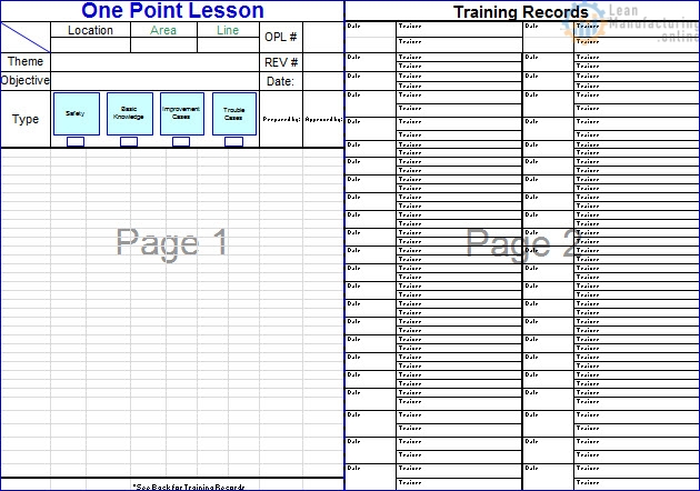
Autonomous Maintenance Step 4 “General Inspections”
Definition Of Step 4 General Inspection
Consists of upgrading the operator’s knowledge and skills related to the machine subsystems, with the intention of eliminating breakdowns due to natural deterioration.
In this step certain activities are developed such as sub system classification and training, putting and solving f-tags ,transferring the knowledge from EM to AM and finally reviewing the CIL standards.

Objective of Step 4
- To improve the knowledge of the operator in understanding the functions and components of the equipment.
- To execute detailed inspections , based on the ability to find abnormalities
- Execute the small repairs.
- How do we do this ??
Updating Inspection Standards
- Using the funnel method we can determine which tasks can be safely transferred to AM from EM(PM)
ex. Inspection and Lubrication, funnelled down AM.

Definitions of the Modules
Prioritizing the Training Modules
- Fasteners – nuts, bolts, screws, tools….
- Transmission – chains, sprockets, moving parts…
- Pneumatics – cylinders, air lines, solenoid valves…
- Electrical/Instrumentation – sensors…
Applying the Training
Training Module 4.2 – DRIVE SYSTEM
Introduction to Drive System
Power transmission:
Power, operated by a procedure in which manual effort is supplemented or replaced by hydraulic, mechanical, or electric means.
Transmission, the transference of force between machines or mechanisms.
This means an electric motor is supplying power to a gearbox, transmitting the force to chains and sprockets further transmitting force to the rollers that move a conveyor or machine.
Power Transmission Module Objectives:
In this module you will learn:
How to identify typical drive assembly components.
- What a gear box is.
- How to inspect a gear box from the outside.
- Chains, sprockets , belts and pulleys.
- How to inspect chains and sprockets.
- How to inspect Poly-Chains and sprockets.
- How to inspect belts and pulleys.
Identifying Typical Drive System Components
Drive systems come in many sizes, shapes and configurations. Below is a typical motor, gearbox, chain and sprocket setup for driving a conveyor.
The motor; it turns at a high speed known as RPM (Revolutions Per Minute) with low torque capabilities. Torque is the amount of force it takes to move or turn something, such as the drive roller that moves a belt on a conveyor.
The gear box; gears reduce the high speed of the motor to a slower more powerful force.
Chains and sprockets; can further decrease the output speed and increase torque to the final destination.
The drive roller; is the last variable in determining the speed of the belt.
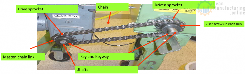
Below is a diagram that will help you to identify the motor, gearbox, sprockets, chains and other key elements of a typical drive assembly.

Gear Boxes
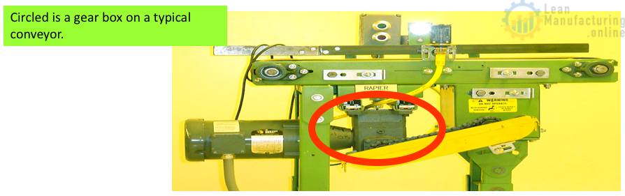
What is a gear box? A gearbox converts the high RPM (Revolutions Per Minute) and low torque of a motor to a slower speed and at the same time increasing the torque (Strength). Gear boxes come in all kinds of shapes and sizes. The one most common to our plant is the the right angle gear box. (Picture above)
In most cases gear boxes are mounted directly to the motor.
Gear boxes are sized by how much output torque is needed and the output speed of the shaft. Output RPM is determined by the ratio of the gear box divided by the input speed.
Example, Gear box ratio = 30 to 1, this means for every time the input shaft spins 30 times the output shaft spins once. If you have a motor hooked to a 30:1 gear box and the motor RPM is 1725. Your formula would look like this; 1725 / 30 = 57.5 RPM gear box output speed. The nameplate on the gear box has all of this information on it. This will enable you to do these types of calculations.
There are many types of gear boxes built in many ways. Examples, 1) Case packer machine has hundreds of gears, shafts and cams moving in different direction all at the same time. 2) A transmission in a car is changing speed by changing gears. 3) All the conveyors in food plant have gear boxes. Gear boxes control the speed and torque of virtually every piece of mechanical equipment in production plant.
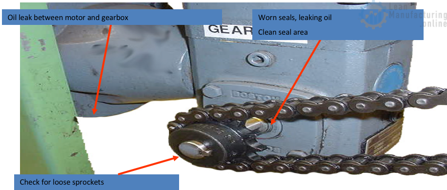
How to Inspect a Gear Box
Like motors, gear boxes are totally enclosed so inspecting the insides is impossible without taking the gear box completely apart. There are however a few checks that can be made on the outside to predict a potential failure.
- Oil leaks, gear boxes are lubricated with oil. The oil needs to be on the inside to get the maximum life from the unit. So check for oil leak around the input and out put shafts.
- Wipe off any dust or dirt that may have accumulated around oil seals. This dirt will eventually wear on the seal creating a gap and letting the oil run out.
- Using caution touch the gear box to check for excessive heat. Too much heat can indicate a bad motor, an overworked gear box, low oil levels, or no oil in the unit itself.
- Check the oil level in the gear box. The ideal method is to use a site glass that is connected to the gear box.
- When the gear box is running listen for unusual noises. Grinding and squeaking are sure signs that something is wrong.
- Look for loose sprockets on the driven shaft.
- If any of these problems exist, contact your mechanic and write an F-Tag.
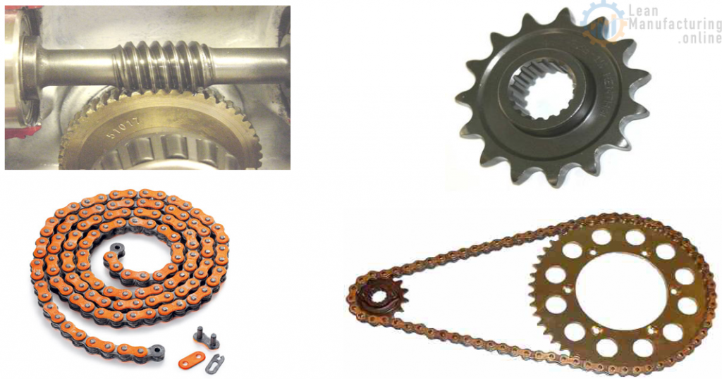
Chains and Sprockets
Chains and sprockets transfer force from the gear box to the machine. By varying the size of the sprockets the speed and torque can be changed. Due to the high friction between chains and sprockets,they need to be checked frequently for wear.
Parts of a chain drive system
It’s very important that you know the parts of a chain drive. Listed below are the main parts of a chain drive system.
Chain and sprocket Inspection.
- Check both sprockets for wear. Are the teeth on the sprockets in good condition.
- Check chain lubrication.
- Check chain condition.
- Check to see if sprockets are loose on the shafts.
- Check keys.
- Check sprockets for alignment
- Check chain tension.
Chain and Sprocket Wear
Two examples of worn sprockets.
This type of wear possibly indicates the sprockets are not in alignment.
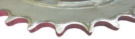
This type of wear indicates the chain is possibly worn. Commonly called “over stretched”.
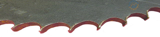
These types of wear can be seen fairly easy and are normally the first things checked. If you have this type of wear, the chains are also probably worn. The sprockets and chains will need to be replaced.
If the sprockets pass the inspection, the next thing you would do is check the chain.
Checking a Chain
It is important to check a chain for the proper lubrication and for wear. A chain with no lubrication will shorten the life of the chain and the sprockets. No lubrication wears out the chains, pins and plates. This wear increases the length of the chain then it will start to wear out the sprockets as well.
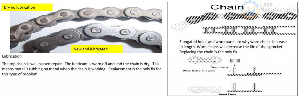
Chain and Sprocket Wear
In order to replace the chain or sprockets you need to know how the chain is put together and what holds the sprockets on. Chains are held together with a Master Link (connecting link). We use several different styles of these, but they do the same thing.
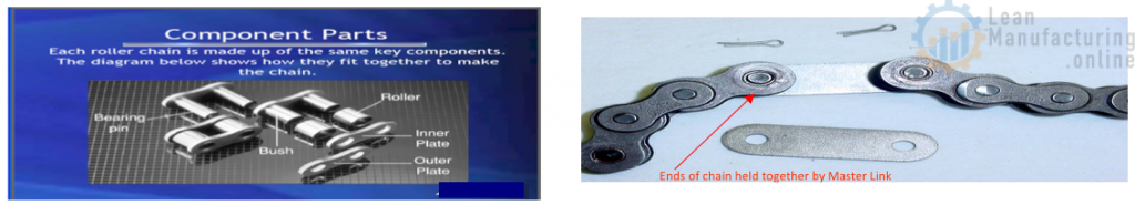
To separate the chain so it can be removed for inspection or replacement, the retainer clip or cotter pins has be removed. This can be done with needle nose pliers. The master links can then be taken apart and the chain removed.
If you see a slack chain on the sprockets it may need replacing. Remove the chain and conduct these two tests.
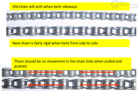
1) Bend the chain sideways. The chain should be stiff, almost rigid when you try to bend it sideways. If it arches like the top one to the right, the chain is bad.
2) Push and pull a chain end to end. If there is any movement or play the chain is bad. A new chain will not have any play end to end.
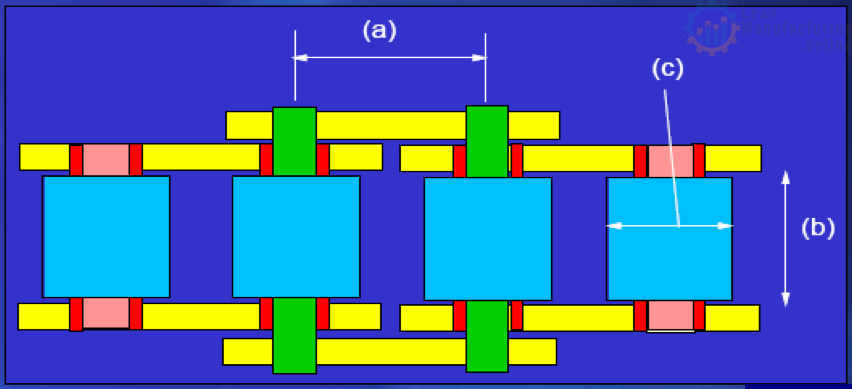
How to identify chain
Normally only 3 measurements are needed to identify a chain:
a) Pitch
(b) Width between inner plates
(c) Roller diameter
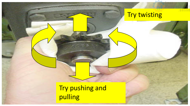
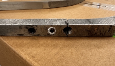
Checking for a Loose Sprocket
It is important that sprockets are secured to the shaft very tight. A loose sprocket will damage both the shaft and sprocket. Once the damage is done the only fix is to replace the damaged part(s). This can be very expensive if the gear box has to be replaced.
To check for a loose sprocket either take the chain off or loosen it so there’s no pressure on the sprocket. Then grab the sprocket and try twisting it back and forth on the shaft then pulling it in and out. If there is any movement on the shaft tighten the set screws. Caution should be taken when grabbing a sprocket. If the sprocket has wear it can create a sharp edge.
Use the proper PPE when conducting inspections:
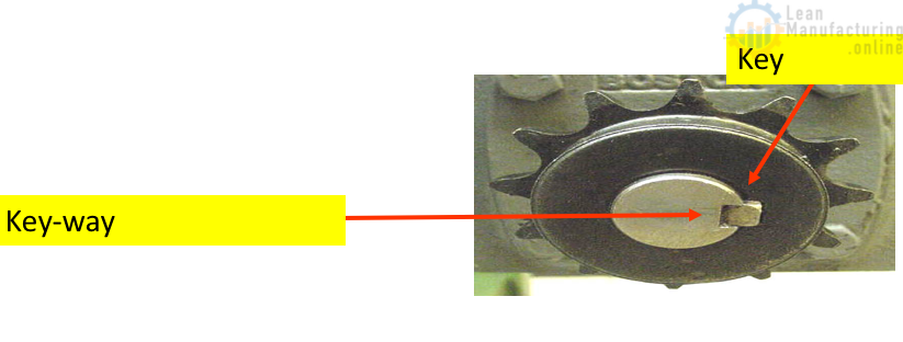
Check the key for being loose, missing or not sitting square in the keyway. Keys have been known to slip out then the sprocket will turn on the shaft. If this happens the shaft will be ruined and the gearbox will have to be replaced.
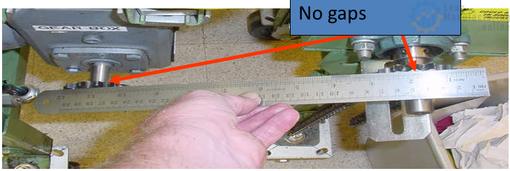
Checking Sprocket Alignment
Place a straightedge across the two surfaces of the sprockets. Make sure there are no gaps between the ruler and sprocket face.

Chain Tension Check
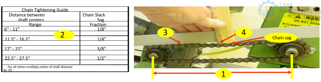
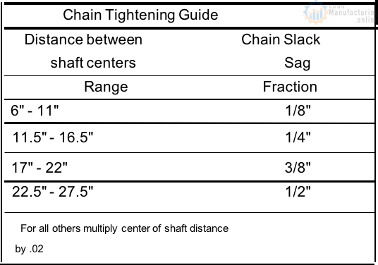
For maximum life of a chain and the sprockets the tension must be correct. The chain slack should be the distance between the two shafts multiplied by .02. Example: 15” X .02 = .3 or 5/16” Or use the handy laminated Chain Slack Guide.
How to check chain tension ?
#1 Measure the distance from the center of one shaft to the center of the other shaft.
#2 Use method A or B below to find the proper chain sag.
- A) Multiply the distance from shaft centers by .02 to get the chain sag distance.
- B) Find the distance from shaft centers in the range on the chart above. Use the fractional number to the right for your allowable chain sag.
#3 Place a straight edge across the top of the chain and sprocket. (Pictured above)
#4 Place a scale (ruler) in the center of the chain next to the straight edge. Push down on the chain with a little force (not hard), measure the gap between the straight edge and chain. Adjust the chain tension until the gap measurement is the same as the measurement you derived in step 2.
Note: Old chains increase in length as they wear, so it is better to replace an old chain than to adjust it. If it has to be adjusted, loosen the drive mounting bolts and slide back until chain is tight. Some units have adjustment bolts or rod for this. Some drive systems have a third sprocket that is moveable or rotates to tighten chain.
Summary
There are 3 major components of a chain drive system:
- Gearbox 2. Chain 3. Sprockets
A Gearbox is used to convert the high speed and low torque of a motor to a slower speed with a higher torque.
Gearbox Inspection:
- Look for oil leaks at the input shaft (where the motor is mounted) and at the output shaft (where the sprocket is mounted).
- Listen when the gearbox is running for unusual noises such as grinding or squeaking.
- Wipe off any accumulation of dust or dirt.
- Check for excessive heat.
Chains and Sprockets transfer force from the gearbox to the machine. Because of the high friction between chains and sprockets, they wear faster and need to be inspected more often.
Sprocket Inspection:
The 2 most common types of wear seen on sprockets are side wear and rounded teeth. Side wear is caused by a misalignment of the sprockets. A worn (stretched) chain causes the teeth to wear off rounded. Either of these will require the sprockets to be replaced.
Chain Wear and Inspection:
If you see a loose chain on a chain drive, it is more than likely worn and needs to be replaced. To check a chain for wear you need to remove it and check for the following:
- Bend the chain sideways. It should be rigid with very little motion side to side.
- Push and pull chain end to end. There should be no movement.
If there is too much side to side motion or end to end motion, the chain should be replaced.
Sprocket Alignment:
To make sure sprockets are aligned properly, place a straight edge on the face of the sprockets. There should be no gap between the sprockets and straight edge. Adjustments should be made if not properly aligned.
Chain Tension:
How to check chain tension:
- Measure the distance from the center of one shaft to the center of the other shaft.
- Use method A or B below to find the proper chain sag.
- A) Multiply the distance from shaft centers by .02 to get the chain sag distance.
- B) Find the distance from the shafts centers in the range on the chart. Us the guide.
- Place a straightedge across the top of the chain and sprockets.
- Place a ruler in the center of the chain next to the straight edge. Push down on the chain with a little force (not hard), measure the gap between the chain and the straight edge. Adjust the chain tension until the gap measurement is the same as the measurement you derived from step 2.
NOTE: Old chains increase in length as they wear, so it is better replace the chain.
Introduction to Belt Drives
Purpose:
- Belt drives exist to transfer energy from one point to the next.
- A Belt is a looped strip of flexible material, used to mechanically link two or more rotating shafts.
- Any mechanism that uses a continuous belt through which power is transmitted.
- A method of power transmission by means of belts that connect pulleys on shafts.
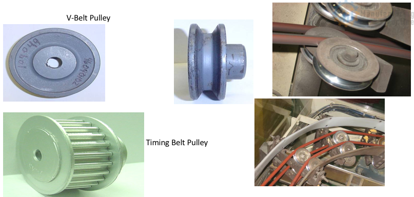
V-Belt or Friction Drives
The V-Belt, hence it’s name has a V shape that enables it to wedge itself firmly into the pulley groove under load. Its’ driving action takes place through frictional contact from the belt and the pulley groove surfaces.
Components
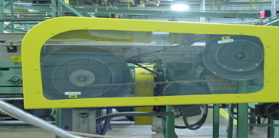
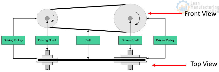
The basic components of a Belt Drive System
– Driving Pulley (attached to a gearbox or motor)
– Driven Pulley
– Belt
Belt Types and Characteristics
A belt is a rotary band that transmits power from one shaft to another. Belts transmit motion and power as do gear trains and chain drives. Conventional belts are made of rubber imbedded with plastic, fiberglass or steel cords.
Belts and Pulleys
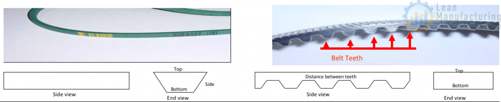
What makes a belt unique:
Belts are identified by their measurements. Width of the top, bottom, and sides and the distance between the teeth on a flat belt. The material the belts are made of is also very important when choosing a belt.
Synchronous Drives
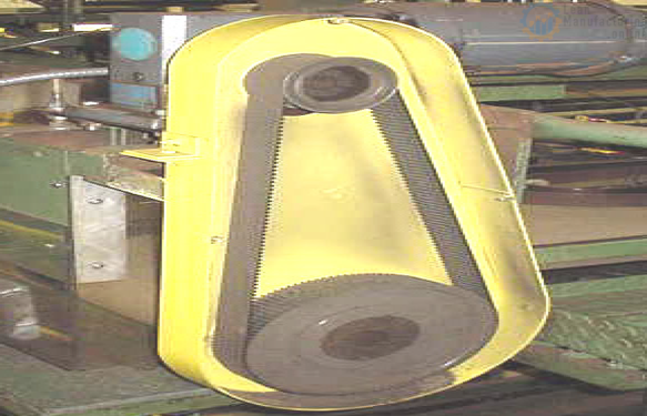
Synchronous Drives combine the flexibility of belt drives with the power of chain and gear drives.Power is transferred by positive engagement of belt teeth with pulley grooves as in chain drives. The positive engagement of belt teeth with pulley grooves eliminates slippage and speed variations. There is no metal to metal contact or lubrication required.
Pulleys
Pulley is :
- A simple machine consisting of a wheel that rotates around a stationary axle. The outer rim of the pulley is grooved to accommodate a rope or chain.
- A rope that moves over a wheel.
- A pulley can help raise a flag to the top of a flagpole.
Pulleys can be made of cast iron, steel or plastic. The groove is normally machined into the solid piece of material. In some cases you will find the pulley keyed to the shaft.
Inspection
When inspecting belt drives, some important things to be concerned about are
– unusual noise or vibration
– loose or damaged guard
– Dust build up
– Dripping grease or oil.
– Worn belt
– Worn or misaligned sheaves (pulleys)
– Worn Drive components such as bearings, shafts, motor mounts and take up rails
– Belt tension
Unusual Noise or Vibration
A good start to an inspection is to first start by looking and listening for any unusual vibration or sound while observing the guarded drive in operation. Any properly installed and operating belt drive system should operate smoothly and quietly.
Dripping grease or oil
Inspect for oil or grease. This may indicate over lubricated bearings. If this material gets on rubber belts, they may swell and become distorted, leading to early belt failure.
Checking Belt
Mark or note a point on the belt and work your way around the belts checking for cracks, frayed spots, cuts or unusual wear patterns. Check the belt for excessive heat. Typically, belts will become warm during operation but, if it is too hot to touch, troubleshooting may be in order. If there are obvious signs of cracking, fraying, unusual wear or loss of teeth in a timing, or synchronous belt, then replace the belt.

Worn or Misaligned Pulleys
It always a good idea to check pulleys and sprockets for proper alignment and mounting. If belts have been removed from the drive, then the pulleys should be checked for wear and damage. To check alignment, all you need is a straight edge or, for drives with long centers, a steel tape.
Below are the common types of misalignments

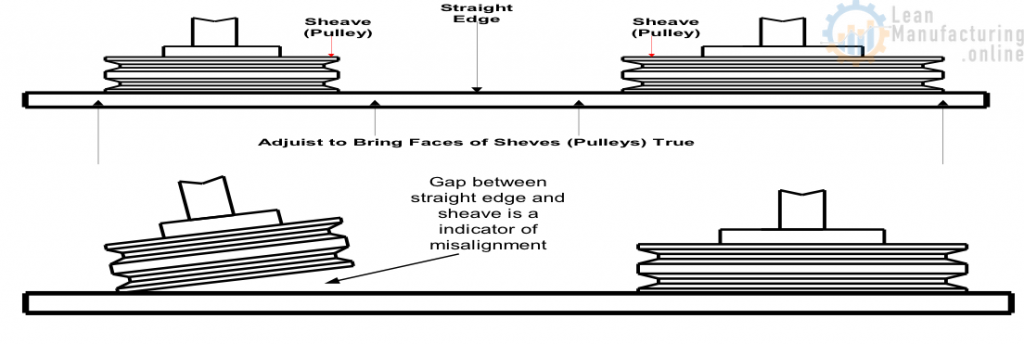
Pulley Alignment and Belt Tension
To correct misalignment, simply:
– Line the straightedge along the outside face of both pulleys
– Misalignment will show up as a gap between the outside face and the straight edge.
Some possible causes of misalignment are
– Motor shafts and driven machine shafts are not parallel (parallel misalignment)
– Pulleys not properly located on the shafts (axial misalignment)
– Pulleys are tilted due to improper mounting (angular misalignment)
Check belt tension :
Check the belt for tension then make a final alignment. Remember that:
– If too little tension is applied, the belts may slip
– If too much tension is applied belt and bearing life will be significantly reduced.
The correct tension is the lowest tension at which belts will run and not slip when the drive is under full load. As a good rule of thumb.

Summary
Belt Drive Systems transfer energy from one point to another.
There are 2 Types of Belt Drives Systems :
- V-belt Drive System
- Synchronous Drive Belt System
It is easy to recognize the difference in these systems. The V-belt looks like it’s name if you were to look at it from the end. It is shaped like a V . The Synch belts are flat with lateral grooves.
The Basic Components of a Belt drive System are:
- Driving Pulley (attached to a motor or gearbox shaft).
- Driven Pulley
- Belt
Just like the Chain and Sprocket Drives, it is just as important to have the proper belt tension and pulley alignment.
Pulleys are aligned the same way as sprockets. Use a straight edge across the faces of the pulleys. There should be no gap between them.
Belt tension is very important. If a belt is too loose it may slip but if the belt is too tight the belt and bearing life is greatly reduced. In most cases a Belt Tensioning Tool should be used to check tension. If you think it is too loose, contact your mechanic.
When doing some basic belt inspections:
- Look at the sides of the belt for wear such as frayed or rough edges. This could be a sign of improper pulley alignment.
- Check the edges or side for being very smooth or shiny. This could be a sign that the belt is slipping.
- Look for cracks or splits in the belts. This is a sign of the belt getting hot which can be caused by the belt slipping.
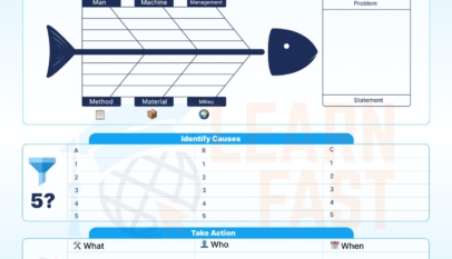


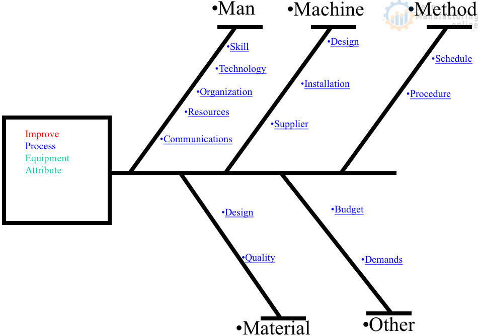
4M Analysis Process: Root Cause Guide for Manufacturing
Learn how to use 4M Analysis to find manufacturing root causes across People, Machine, Method, and Material with diagrams, examples, and checklist.