Required quality
When a consumer purchases a product, she purchases not just the object itself but the effects, or functional
quality, that object can provide.
These effects include tangible or “true quality” such as the ability to cut things, write words and so forth.
However, consumers also require non-functional quality, such as appearance and design.
We call these aspects of quality “sensual quality.”
How products exhibit quality
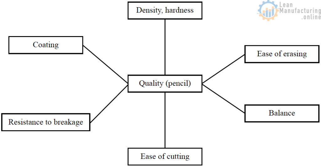
Quality and quality characteristics
Appropriate yardsticks are needed to measure quality. For example, the quality of a pencil can be
measured by the density, hardness, resistance to breaking and ease of cutting of the graphite in the pencil.
These yardsticks used to measure quality are called quality characteristics.
These quality characteristics can be measured and observed. To enable them to be processed and
manipulated by statistical and other useful techniques, quality characteristics should as far as possible be
expressed numerically.
In the example of the pencil, these numbers should refer to the hardness of the graphite, its resistance to
breakage, and so forth.
The numbers used to express quality characteristics are called quality characteristic values.
Basic schematic view of standards documents for process management
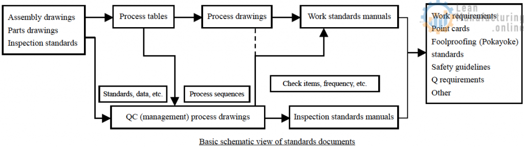
* Standards documents are documents used to indicate work directions or manage the support of manufacturing quality. They include process tables, process drawings, QC process drawings (management process drawings), work standards documents, point cards, Q requirements and much more.
Process tables:
Process tables are tables indicating production methods, specific sequences of action, the machines used and so forth, based on design drawings. The design drawings form the criteria on which the process tables are prepared.
Process drawings:
These drawings are based on the process tables and indicate the quality characteristics to be built into each process, the necessary standards, the tools to be used, and the instruments used to check the quality characteristics. These are prepared based on the design drawings and process tables.
QC process tables (management process drawings):
These tables indicate specifically who manages what, when, and how, in process management, and organizes these requirements in a drawing according to the flow of processes.
Work standards documents:
The work standards documents are drawn up by the manufacturing division to standardize the contents of the process drawings and indicate the work procedures by which the work is carried out (including operation procedures, machine setting methods, adjustment procedures, adjustment methods and replacement of jigs and tools), as well as items requiring quality checks and the frequency of those checks, foolproofing and safety points. These are prepared based on the process drawings but the quality check items are prepared based on the QC process tables (drawings).
Inspection standards documents:
The inspection standards documents determine the standards for quality judgment as well as the specific methods to be used for inspection. Depending on the processes to which they apply, these include shipping inspection standards documents, receiving inspection standards documents and auditing inspection standards documents, among others. They are prepared based on QC process tables (drawings) and design drawings.
Work requirements:
The work requirements describe in more specific detail the key points of the work listed in the work standards documents. Depending on the content, these are named according to the work to which they refer and may be called the setup requirements, foolproofing requirements, etc.
Point cards:
These cards list cautions, key points and so forth, mainly serving as warnings about the work.
Q requirements:
These are used to set deadlines and limits to ensure that work cautions are thoroughly observed when quality trouble occurs.
Preparing QC process drawings
1. Contents of QC process drawings
QC process drawings indicate how the manufacturing division and inspection division check the quality characteristics of products in the production sequence, as well as the quality assurance methods used as tools to manage how well quality is assured. They are used to provide a comprehensive assessment of quality assurance activities across the entire manufacturing process.
2. Preparing the QC process drawings
2-1 Formats
In principle, QC process drawings provide a contrast between attached tables 1 and 2. If the customer provides a list of instructions, the QC process drawings follow these instructions.
2-2 Required descriptions
1. Definition of terms
1) Management items
Management items are items stipulated in drawings, product specifications and the like as quality assurance characteristics. They are the characteristics of the results of production processes that must be checked to ensure that the process (work) is carried out according to standards.
2) Inspection items
Inspection items are factors that must be checked because they are thought to have significant impact on the quality assurance characteristics in the manufacturing process.
2. Items listed in attached table 1
* Process: Indicates processing, assembly, casting, etc.
* Model: Indicates the product model.
* Part/product number: Code number of the part or product.
* Product name: Name of the part or product.
* Quality grade: Indicates the quality grade.
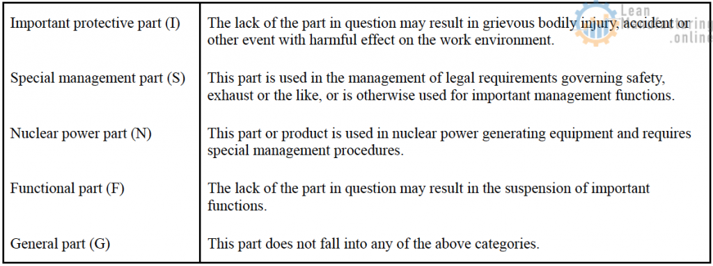
Parts fall into one of the following five categories according to the importance of their features (quality characteristics).
* Control number: Number determined by the division that produced or issued the part
* Date: Date on which the part was produced
* System drawing: This is a process flowchart created using standard process management symbols such as those described in JIS Z 8206.
(Process sequence) Draw a schematic view of the completely finished part or product in the blank space.
* Revision history: If the schematic view has been revised, write the revision notification number, date of revision and description of the revision.
* Model number: Write the model numbers of products that follow the same processes and are managed in the same way.
* Destination: Write the destinations of the products and parts and the number of items sent.
3. Items indicated in attached list 2
* Model number: Same as in attached table 1
* Name: Same as in attached table 1
* Quality grade: Same as in attached table 1
* Control number: Same as in attached table 1
* System drawing: Write the process sequence for the system drawing in attached table 1 using the process description symbols.
* Process name and overview: Write the process names in the same order as the process description symbols in the system drawing. Also indicate an overview, the parts names and the names of equipment and machinery.
* Management items: Write the items that need to be managed in the process as quality assurance characteristics.
* Standards (management levels): Write the items stipulated in drawings and specifications or the level of each management item.
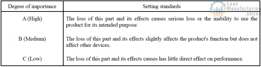
* Degree of importance: Classify management items according to degree of importance using the following three categories.
Indicate important protective part, special management part or nuclear power part as necessary in the degree of importance column for each management item if the importance characteristics of “Important management part (I),” “Special management part (S)” or “Nuclear power generation part (N)” apply.
* Division verified: Write the equipment division for which management items and inspection items are verified. Place a check beside either manufacturing or inspection. If confirmation is conducted using both, place a check beside both.
* Autonomous check: Write management items for protective characteristics: Methods of measurement and inspection, frequency of confirmation, quantity confirmed and recording method.
* Factor check: Write the method of confirmation, criteria, frequency of confirmation quantity confirmed and recording method for factors with an especially strong impact on quality.
* Inspecting-division column: Write the methods of measurement and inspection, frequency of confirmation, quantity confirmed and recording method used by the inspecting division as management items for assurance characteristics.
* Related standards: Write the names of standards used in the process and the control numbers. This is not necessary if the standards can already be searched using the model numbers and process numbers in the process drawings and work standards documents.
Setting processes and drawing flowcharts
(1) Method of setting flowcharts
1) What do we mean by the terms “process” and ‘work”?
(a) A “process” is any step in processing or checking in which materials and parts are received.
(b) Work is what workers do.
(c) Normally, therefore, work occurs within processes. However, in process industry some processes do not involve workers.
2) Determining the extent of a single process
Processes are determined differently in parts industry and process industry
(a) In parts industry
The length of one process is the work of a worker through a single cycle.
* In cutting processing, a single process consists of checking the material, setting the blade, conducting a test cut, measuring, adjusting the blade position, measuring again, and confirming product acceptability. This entire set of actions is referred to as the “cutting process”; the individual steps are not set as processes.
* In assembly processes, each of the following is regarded as a single process:
– Mounting the part, tightening the screws and checking appearance
– Adjusting function
– Testing the product
(b) In process industry
* A process is any action in which the form of a material is changed or in which a quality step occurs. A “quality step” is an action such as introduction of material, mixing, reacting, firing, separating, inspection or product shipping; each of the foregoing items is considered a process.
(c) Whether the receiving inspection of materials and parts is viewed as a step depends on each case. If a product has undergone receiving inspection and is already in inventory, receiving inspection is not counted as a step in a single process; rather, the process begins when the product is shipped. However, this is only so if the product to be shipped requires quality assurance confirmation. If it does not, the process begins with the first processing. In the case of custom order-based production, the process begins with receiving inspection if special quality confirmation is required during receiving inspection.
(2) Drawing flowcharts
1) Flowchart drawing is the start of production of a QC process drawing. The steps of the process must be
decided before drawing can begin.
2) Process drawing symbols must be used to draw the flowchart, as stipulated in JIS Z 8206.
3) Sequence for writing flowcharts
Before starting to write, determine the main flow of the flowchart.
Before drawing process flowcharts, determine the main parts and materials and use these to draw the main flow of processing. Next, add the materials and parts assembly as branches feeding into the main flow.
* Whereas in parts industry, flowcharts must be drawn for each part, in process industry a single sheet of paper should be sufficient to draw the flows for all processes in the plant. When indicating a given product’s manufacturing processes, photocopy a single-page flowchart and draw the paths that flow through it using red lines.
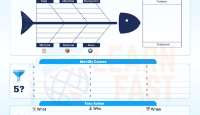


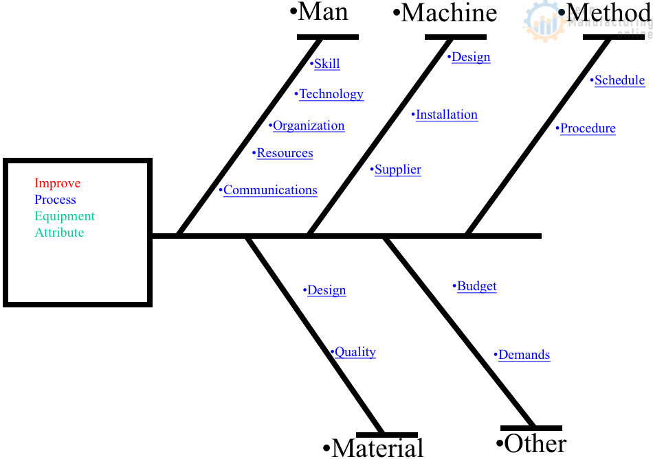
4M Analysis Process: Root Cause Guide for Manufacturing
Learn how to use 4M Analysis to find manufacturing root causes across People, Machine, Method, and Material with diagrams, examples, and checklist.